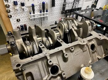
OK! It is about time I got started with ERE-383
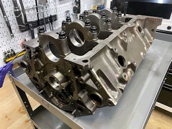
#96. This is the "budget" main cap version which is
hardly budget. The main caps are pretty good. They are
4-bolt but not billet steel. ARP main studs are used which
helps beef things up. Here is the block and I'm beginning to
get it ready for paint. I put on sacrificial rear main seal
and timing cover and oil pan to help me mask off areas. I wipe
it down with acetone (or brake clean). The paint is the
Eastwood 2 part "2K" high temp ceramic.
|
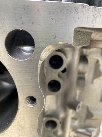
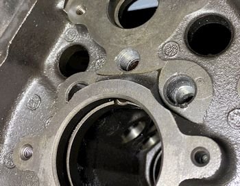
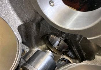
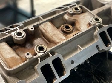
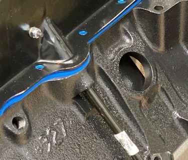
Here is the drivers side front of block where some head gaskets
block and restrict the oil drain-back. I always clearance in this
area no matter what head gasket is used.
|

|
Painting finished. Next on the agenda is rotating assembly
mock-up to check for clearance.
|

|
Ok, moving forward. It is time for engine #96. Today
I'm going to tap the front oil galleys for threaded plugs and
clearance the bottom of the bores for rod clearance at the
cam-tunnel side. Then clean the block, assemble
crank/rods/pistons to make sure all clears. Possibly I'll need
to do further clearancing. Cam bearings will be installed
after I know that there will be no more need to grind on the block.
|
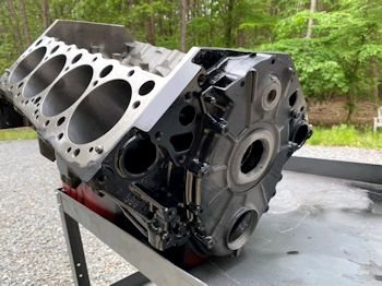
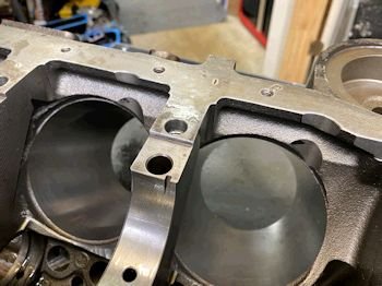
Here is the block after I clearanced at the cam tunnel area for
rod stroke. Notice it is no longer painted. The pressure
washer was taking off the paint. I must have prepared the
block poorly for accepting paint. Better that happens to me
than the customer. I'll do a better job with the next paint
job.
|
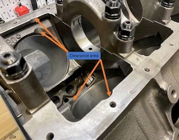
See the areas that are typically clearanced for rod stroke. It
is the bottom of the cylinders inboard and outboard. You won't truly
know that the clearance is enough until you mock up the rotating
assembly. That is today's goal.
|
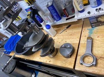
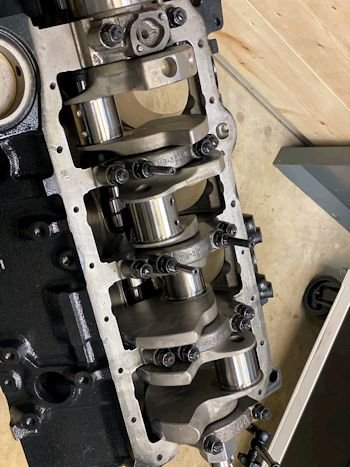
Here is the 4340 forged steel Eagle crankshaft, (Neutral
balanced) at 1759g by Eagle.
|
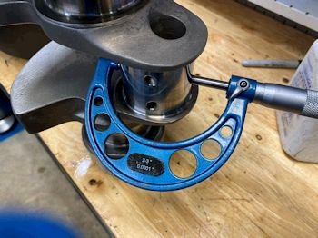
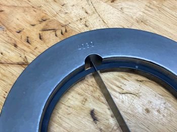
I might as well measure rod and main clearance while I mock up
the rotating assembly. Rods are all at 2.0992"
|
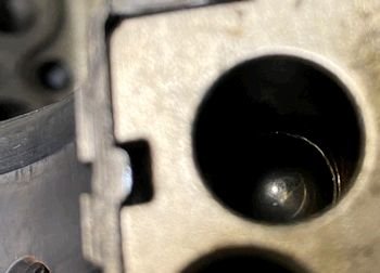
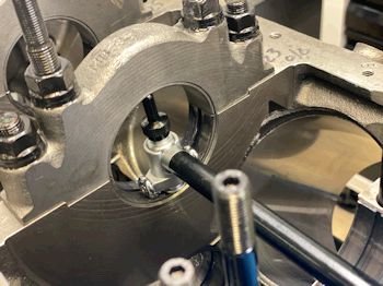
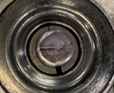
Photo for proof that I installed the oil galley ball.
|
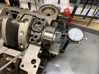
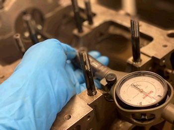
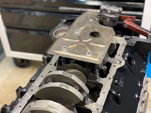
I put the crank in with just #1 and #5 caps and while I'm at it
I checked #5 thrust bearing with feeler and by dial bore.
.005" by feeler on each side and .007" end play by dial
gauge.
|

|
Assembly of #1 piston and rod and King CR807XPN bearings.
(Standard Size). All rods are from .023 to .027"
clearance.
|

|
The 1st rod mock up, (#1), is good. The rest were ok but a
few were too close for my comfort. I have the areas marked for
grinding, (tomorrow).
|
I run into trouble with Eagle rods almost every time. The
outside edge of the pin bushing is too tight but only the outside
edge. All the rods seems to have a lip that needs to be buffed
to allow the pin to pass and fit nicely in the bushing.
|
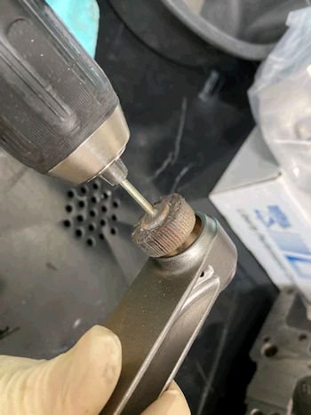
I do this by hand.
|
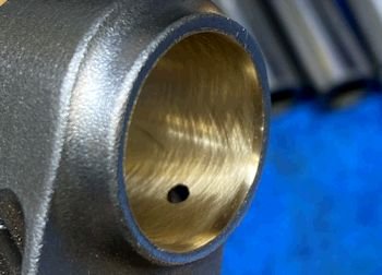
See that just the outer edge of the bushing is buffed. Now
the piston wrist pins fits perfectly (on all 8 rods).
|

|
All mocked up. Now to removed the pistons/rods and crank.
|
Before I re-grind and re-paint I'll check all main cap bearing
clearance. King MB557XP bearings.
|
From .022" at #1 main all the way to .035" at #5 main.
|

|
Here are the sharpee marks where I need to grind some
more. I'll do that tomorrow and also paint.
|

|
Ring filing. Going with .020" 1st ring and .020"
second ring for hot street power and occasional strip.
|
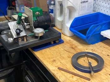
Here is my trusty ring filing set up.
|

|

|
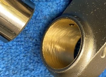
Cam bearings going in. Allen key-wrench to verify oil hole
alignment.
|

|

|
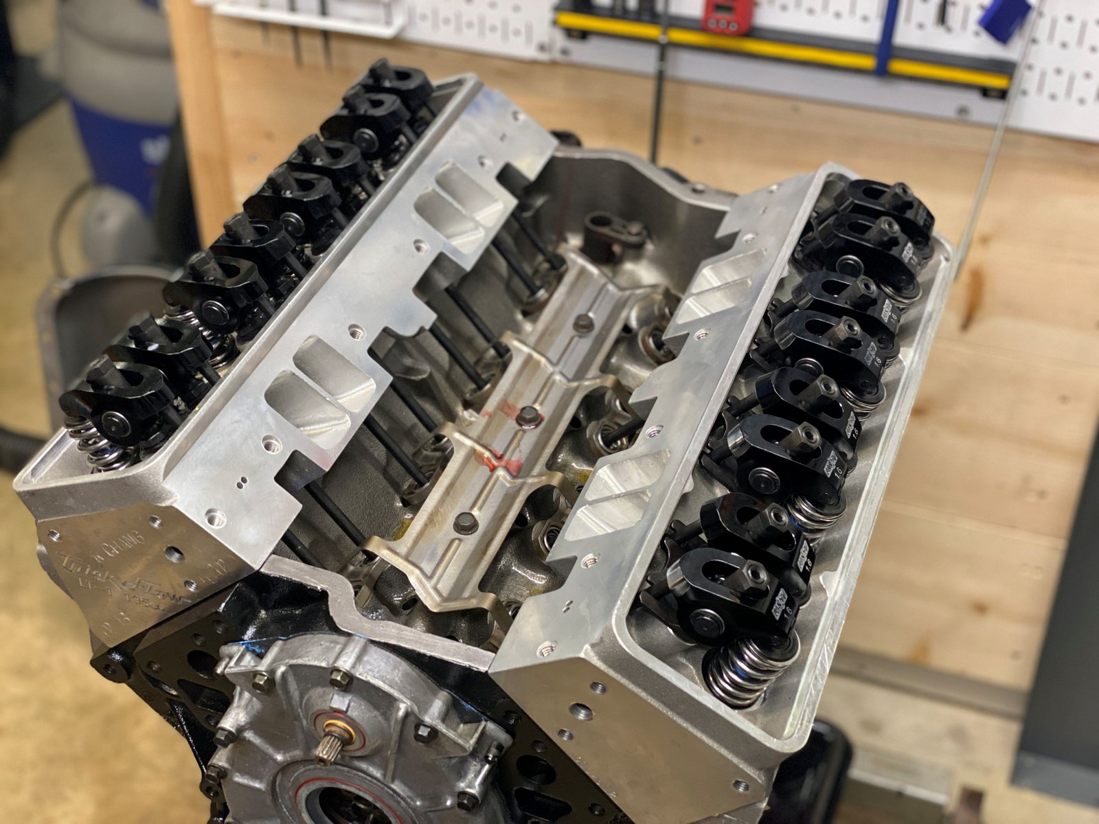
Camshaft installed (and used but good water pump drive and new
Cloyes gear). The camshaft is Lloyd Elliott from Lunati.
A streetable 231/239/112 duration @0.050" and .571/.587"
lift with 1.6 rockers.
|

|
Thrust is .006 after torquing down the rear cap.
|

|
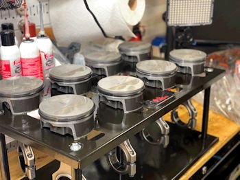
Pistons ready for the rings.
|

|
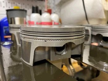
One problem piston. Look closely at the 2nd ring land and
see a deformity. Could I have mishandled it and dented
it? Possible but I don't see any scratches or "dent"
witness marks. 1st time I've seen any blemish from
Mahle. Anyway...that's the breaks. I will be getting a
replacement on order Monday.
|
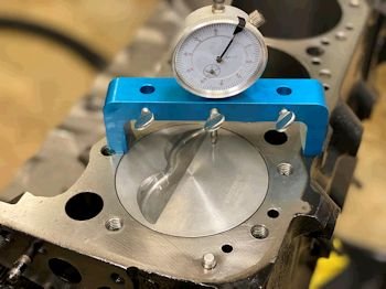
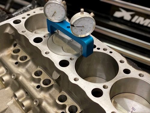
In the interim while I wait for the 1 piston I can check deck
height. I measure in the center and on both fore and aft of
the piston and take the average. The piston rocks in the
bore. .010" aft and .014" forward. (we'll go with
.012"). That makes static compression ratio 11.05:1 with
FelPro 1074 head gasket. (if the heads are 62cc). I'll measure
the head chamber soon.
|

OK, the new piston arrived and it is installed, (no
photo). Here is the beginning of camshaft degree
verification. Intake centerline measured at 108.5* and the cam
card spec is 108. This is an LE camshaft with
.571"/.587" lift and 231/239 duration @ .050" and
112* lobe separation.
|

|
Then I went to the rest of the pistons to verify how far the
pistons were in the hole. They are all in the hole 0.012"
(give or take .001").
|
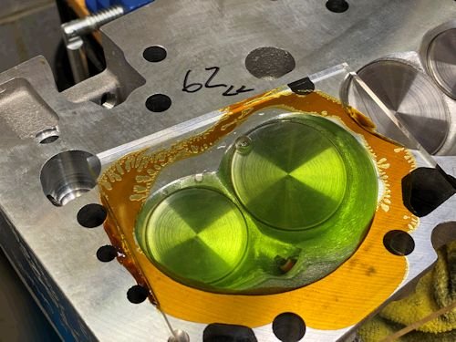
Now I measure one chamber to get the combustion chamber
volume. I measured 62cc. That puts static compression
ratio at 11.05 with the FelPro 1074 head gasket and -5cc piston and
-.012" piston-in-the-hole.
|

|

|

|
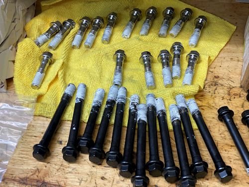
ARP head bolts with stainless outer bolts.
|
torqued to 70ft-lb
|

|
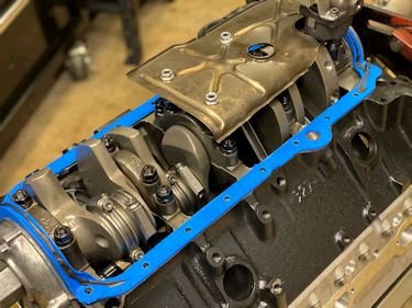
Oil pump and windage tray installation. The oil pump is
the Melling 10554ST which is the premium shark tooth. Standard
volume.
|
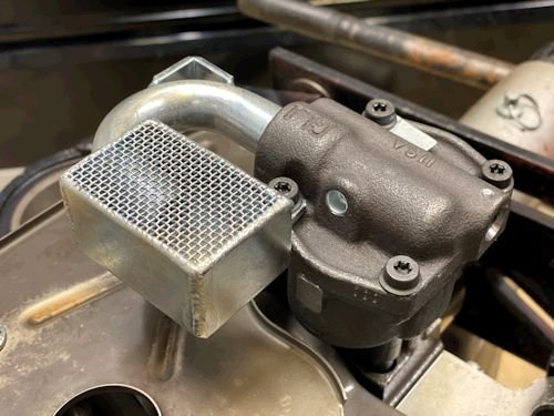
Canton oil pump pickup.
|

|
Oops. Now I notice that the oil pan is 8" deep.
This pickup I have is for a stock pan at 7". Always
measure. I'll have an 8" pickup in a few days.
|

|

|
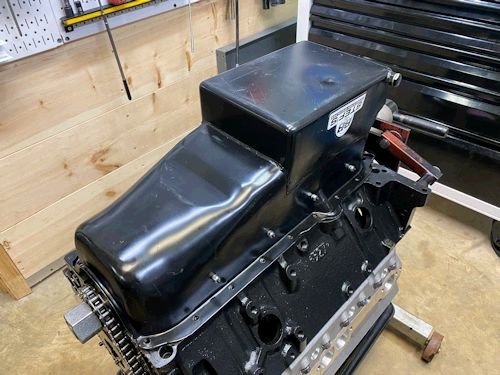
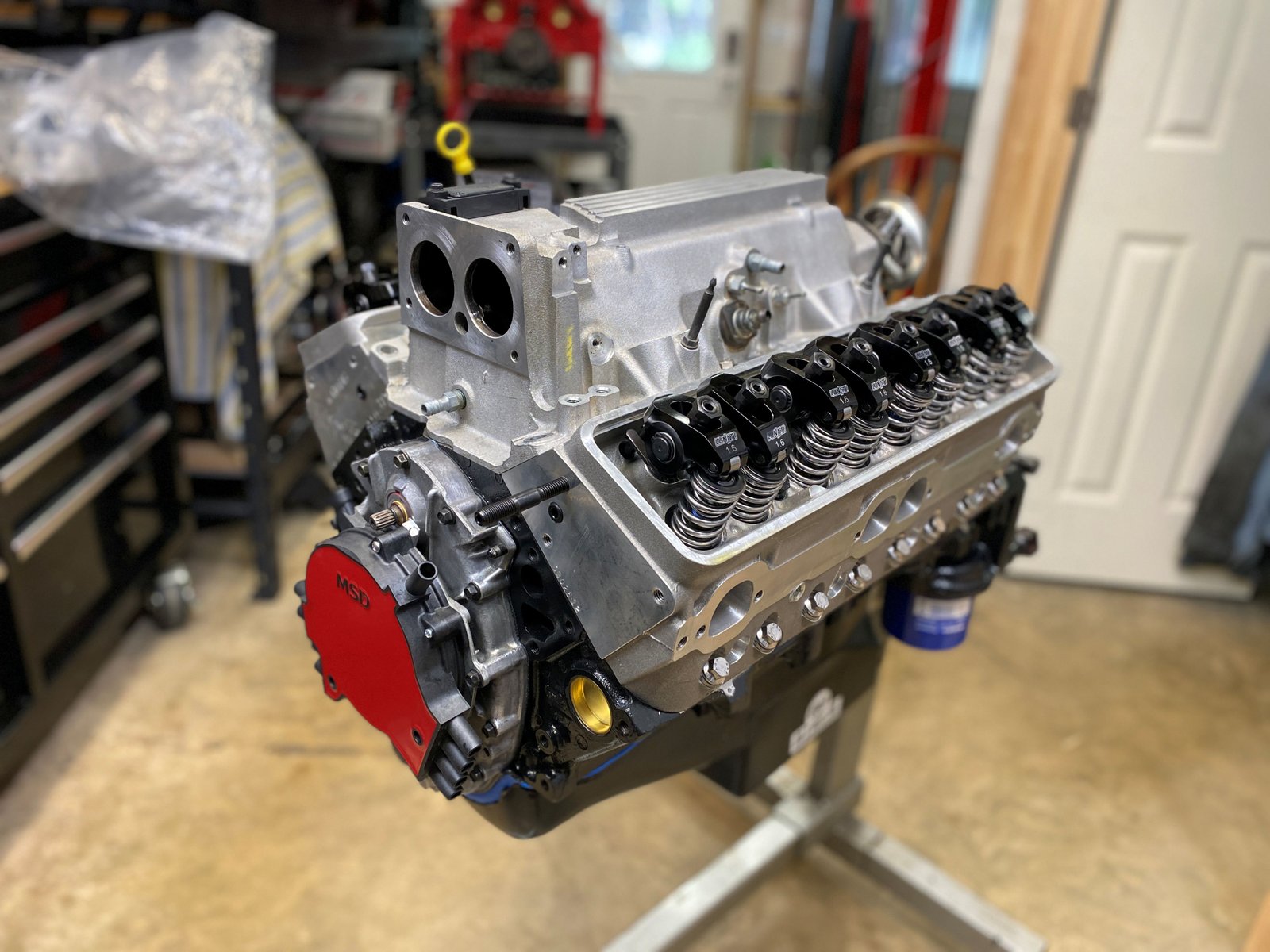
For now I put the oil pan on as a dust cover. Check back
in a few days when I have the 8" oil pump pickup. The
engine is almost finished.
|
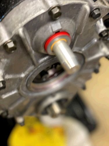
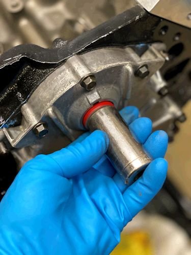
Timing cover on. Now installing the seals. This is
my water pump seal installation tool. Tapered nose to allow
the seal to slide on...
|
...then hammer it home with a socket.
|

|
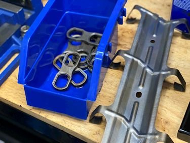
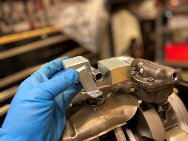
Used (core) lifter hardware. Cleaned up and ready for
installation.
|
The lifters are my favorite stock style replacement. These
are Crower 66330-16
|
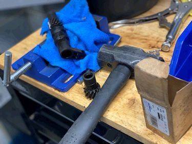
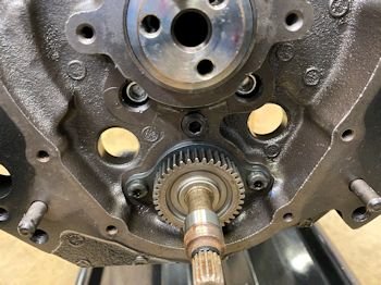
The oil pump drive gear gets a new ACDelco gear.
|
Installed the oil pump drive gear just temporary. I want
to make sure all is good. Later it will be removed in order to
spin the oil pump with a drill.
|
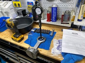
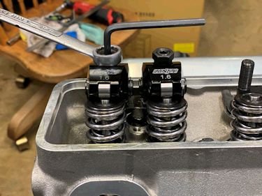
Now testing for pushrod length with my Lunati pushrod length
gauge. It comes out to 7.180" and then add the lifter
preload of 1/2 turn (.025") and you get dang near 7.200"
pushrod. Remembering that the 7/16" stud is 20 threads
per inch and lifter preload should between .020" and
.060". Just know that 1 full turn on this 7/16"
rocker stud is .050" of travel and so you can do 1/2 to 1 full
turn of lifter pre-load.
|
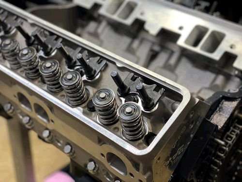
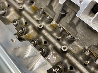
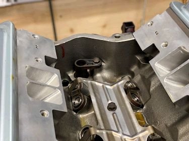
The Lunati lifters sit pretty good on the valve tips. The
guide plates were installed by Lloyd Elliott and he did a good job.
These are Lunati 15315-16
|
A quick test of the rocker tip to valve tip shows A-OK.
|

|

|
Cleaning up parts. I take the tin pan off the bottom of the
manifold just in case there is debris or sludge in here. It
was not all too bad but this photo is taken after a round of
cleaning.
|
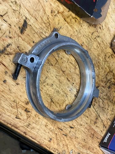
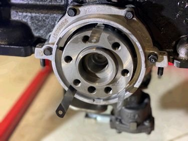
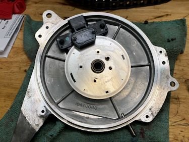
Cleaned up a core rear main seal housing.
|
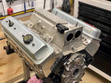
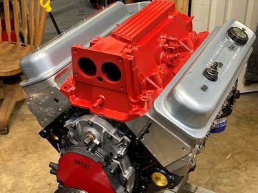
The intake is on temporarily to act as a dust cover. Also the
fit can be looked at to see if the bolt holes line up and the
china-wall and head mating angle. All is good with this
manifold.
|
.003" (and sometimes a .004") feeler gauge at the
alignment nubs while tightening the bolts.
|
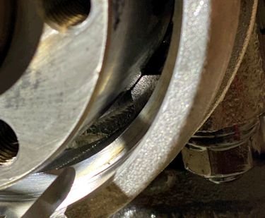
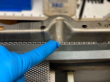
This is a close up of one of three nubs. That is a .004"
gap. All 3 nubs have a .004" gap. That ensure the
housing is center and the seal won't leak.
|
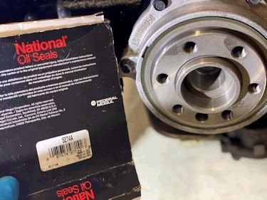
Speaking of seals this is new to me, (customer provided). The
National Oil Seals brand. It seems to be pretty good quality.
|
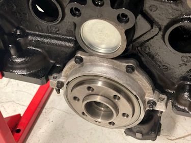
And this is a photo of the camshaft plug and rear oil galley plugs.
|
New oil pump pickup is here. This is for an 8" pan
and also "drag-racing" style which keeps the pickup
further back. This was needed due to the oil pan having a trap
door baffle in the spot that a stock pickup would want to be.
|
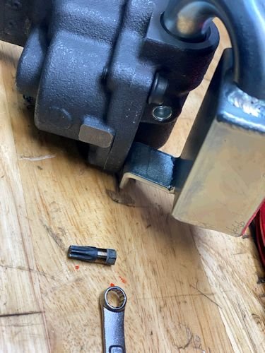
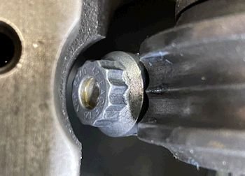
I made this special little stubby nub of a torx bit in order to
fit under the pickup and to be able to tighten down the oil pump
fastener.
|
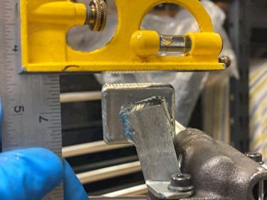
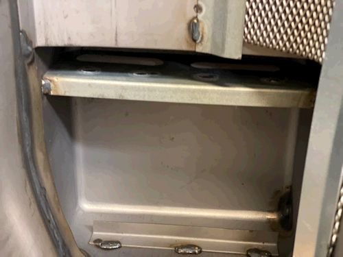
Hard to see here but the pan is 8.0" deep and the pickup
goes to 7.50" depth. That gives 1/2"
clearance. A bit larger than usual but not out-of-spec.
|
I hope this screen does not interfere with the dip stick
tube. We will soon find out.
|
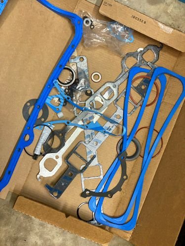
Wow! What I thought was an oil pan gasket turned out to be
a box of multiple gaskets. The box was previously opened and
the gaskets looked to be touched by grimy hands but they are still
good after cleaning.
|
Dip stick tube fits well and does not hit that oil pan screen
|

|
One last look at the bottom end. I put RTV on the gasket
at the corners just in case the pan does not fit exactly
perfect. It's an unknown pan to me. Although stock style
pan, (like this one), fit best and seldom need RTV to seal up...I
went conservative here and used RTV. If possible it is nice to
not use RTV in order to be able to remove the pan in the future.
|
Putting on an MSD cap and rotor. First I made sure to
clean the base and then blow it dry.
|
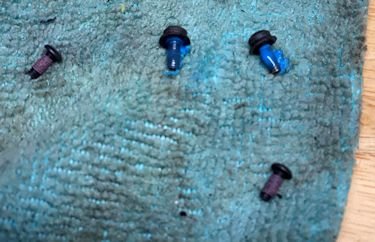
Also always reuse the stock rotor screws and put loctite on the
threads.
|

Later today I'm going to paint the intake manifold.
|

|

|

|
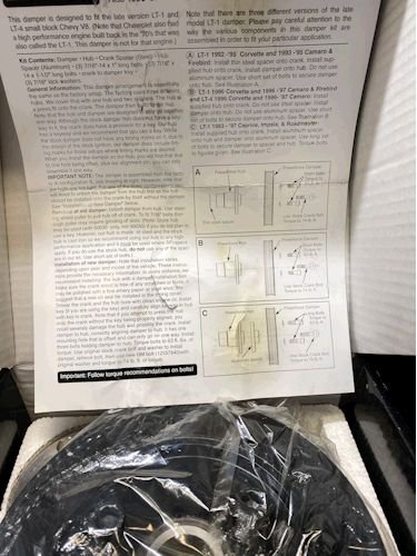
I took a photo of the Professional Products damper #80030
because I really like how you can cover all the LT1 engines with one
part number. They have all fitment covered, from Fbody to
Bbody to Ybody, (but not LT4) It is a reasonably priced unit
for pretty good quality.
|
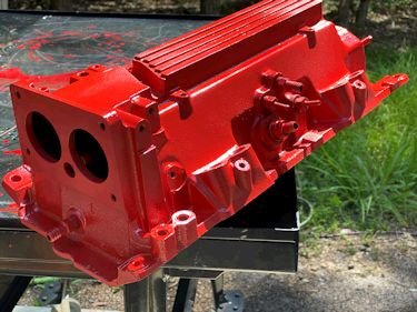
This is DE1653-RED from Dupi-Color (Engine paint).
|
I wish it were more Red and less Orange.
|
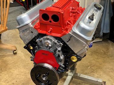
Looks pretty good I think. But if it could be a red as the
MSD Opti that would be AWESOME.
|
|