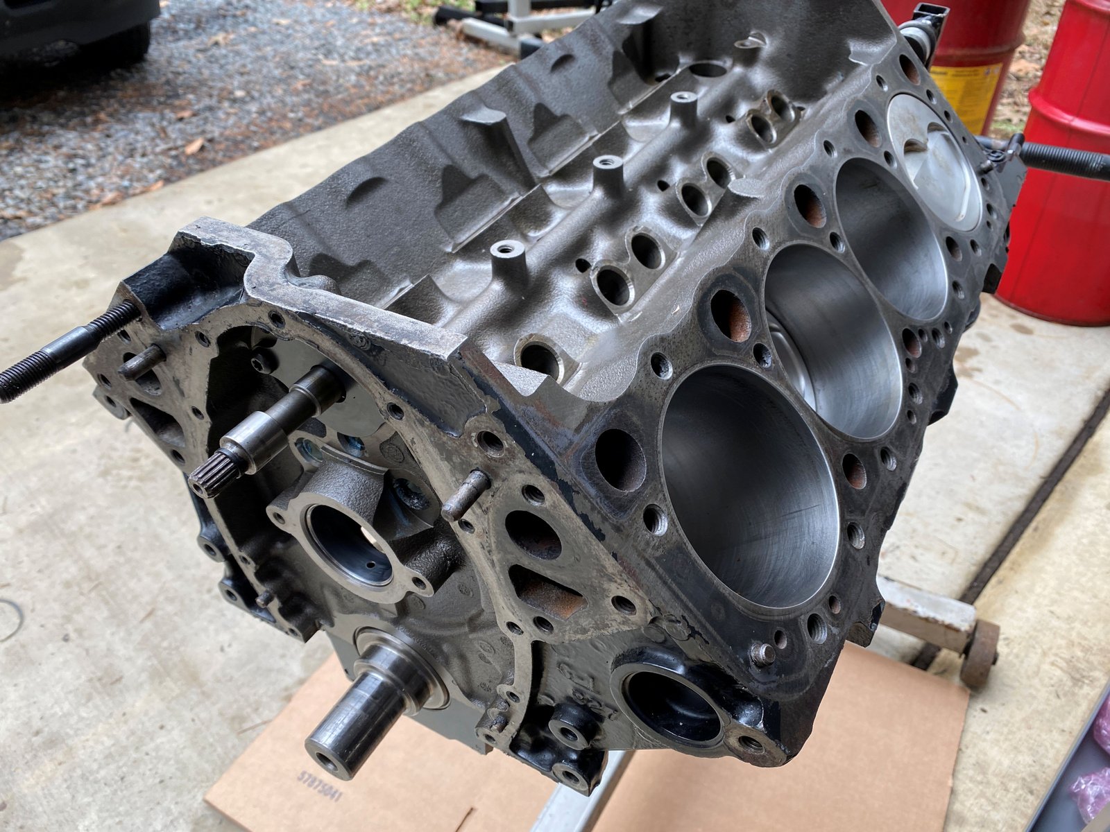
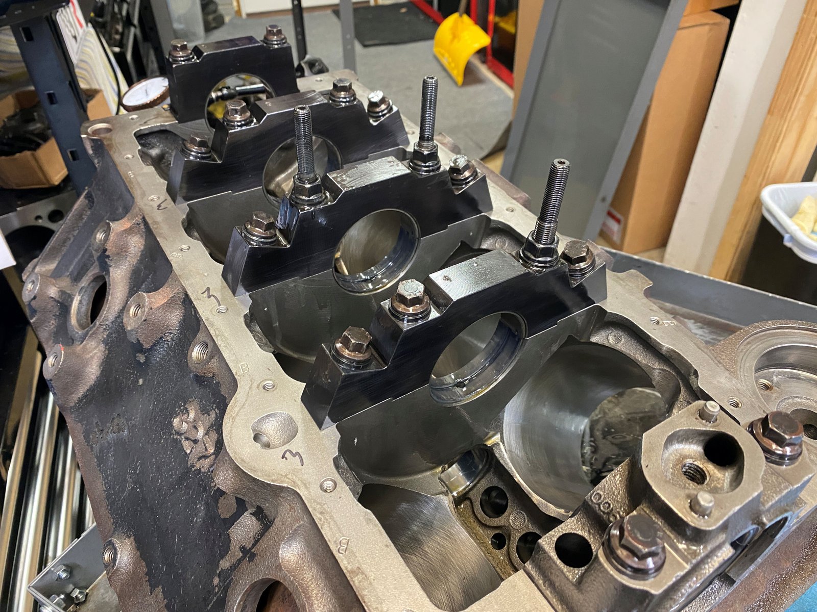
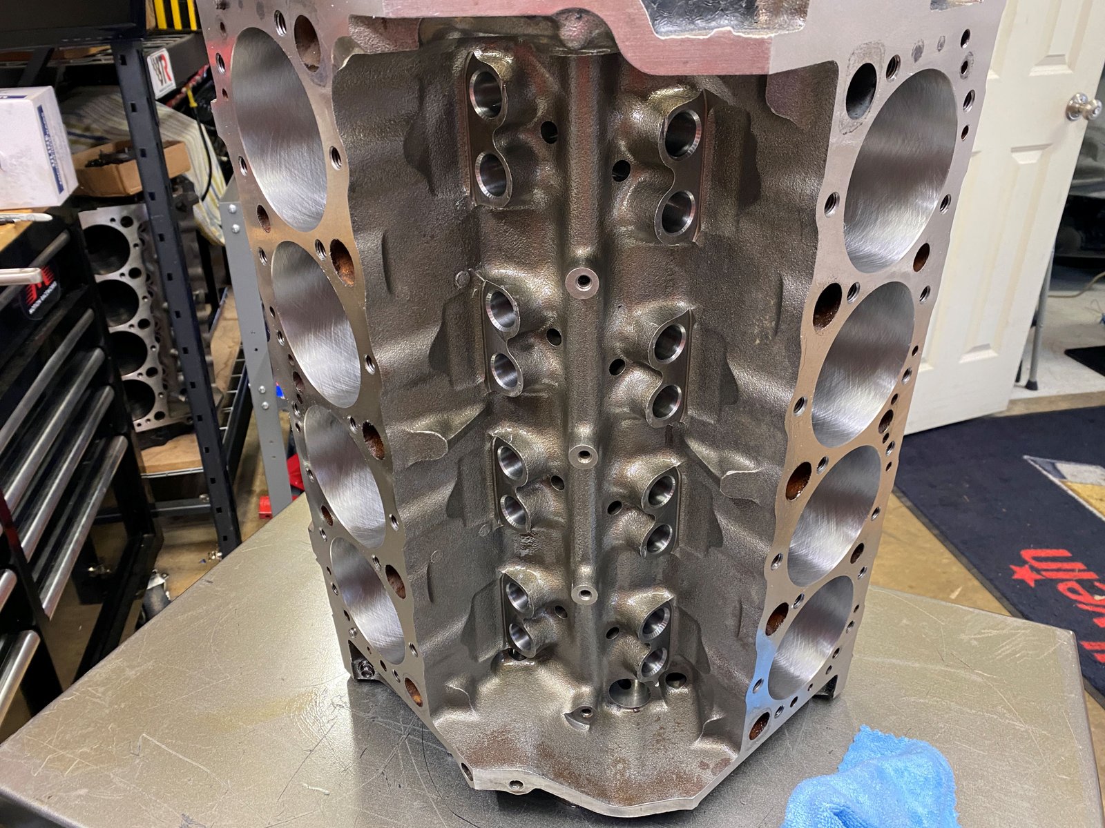
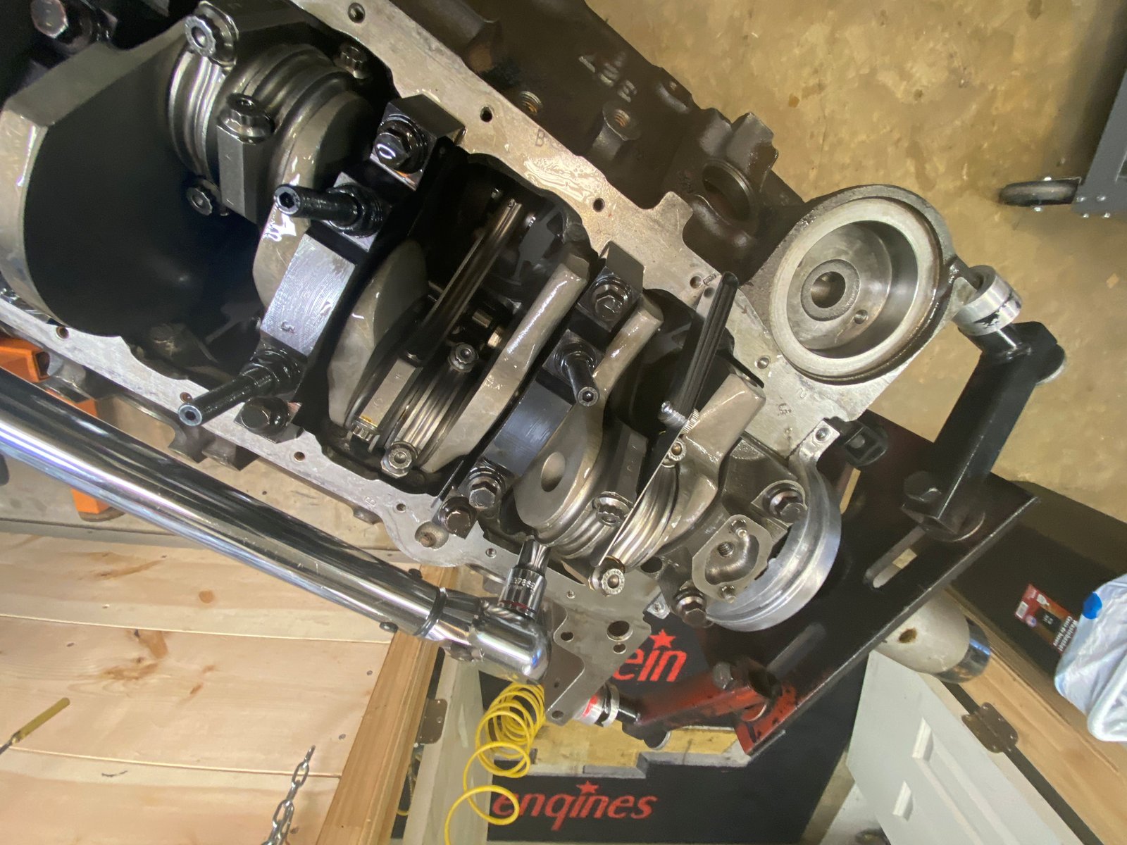
The block is advertised as square decked, 4.030" over,
Forged Eagle 396 rotating assembly with custom pistons, Splayed main
caps. Looks good.
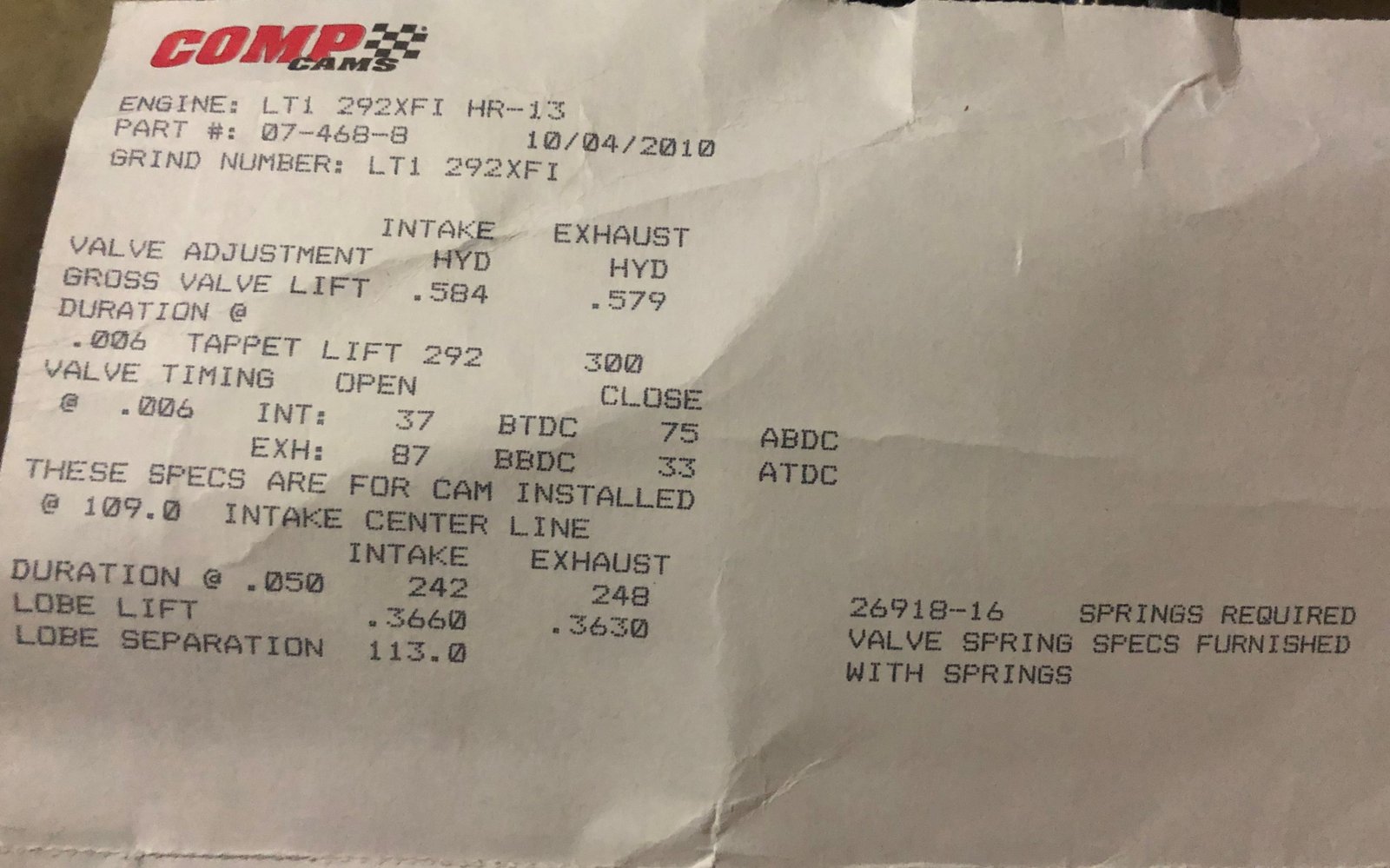
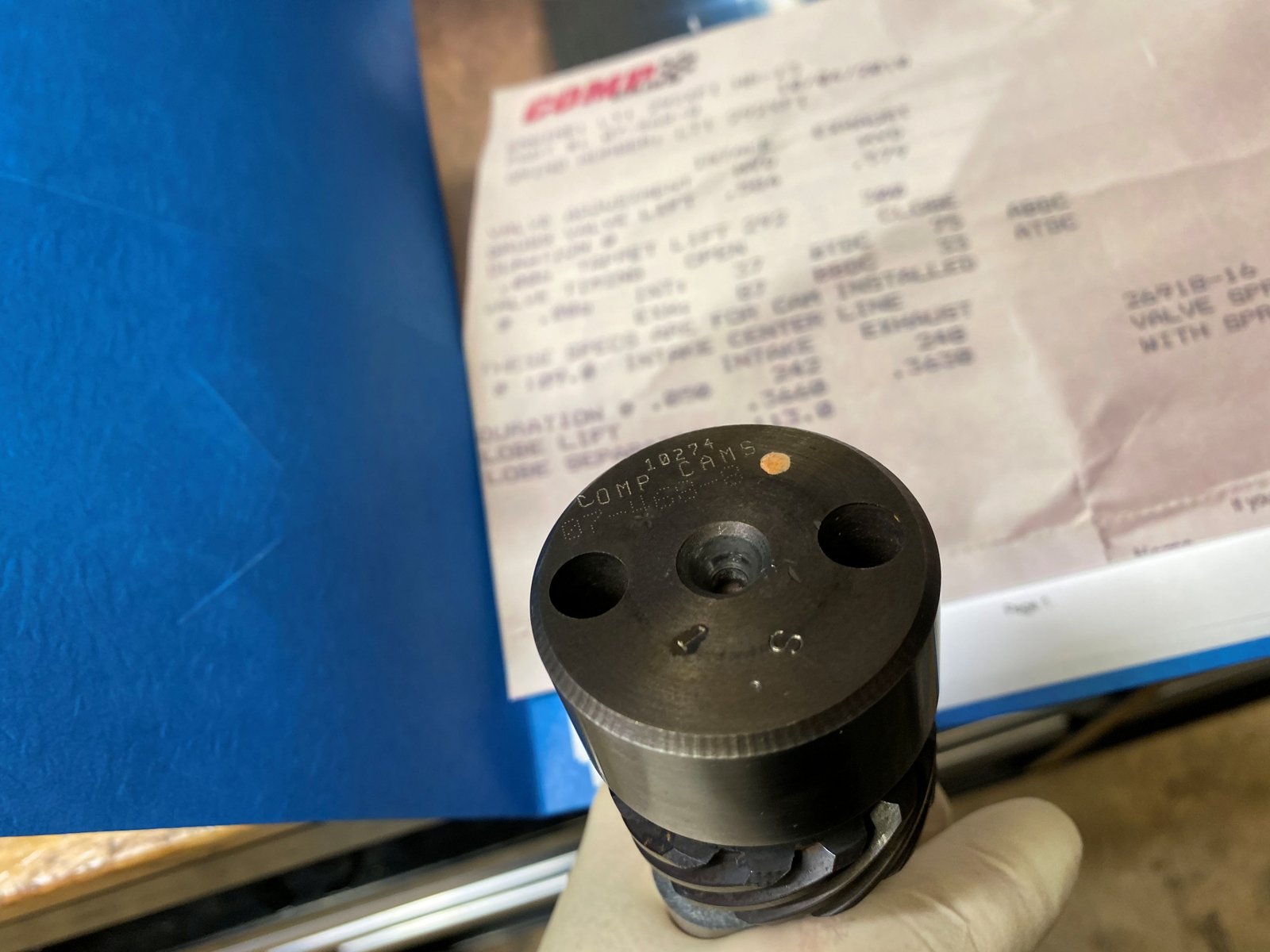
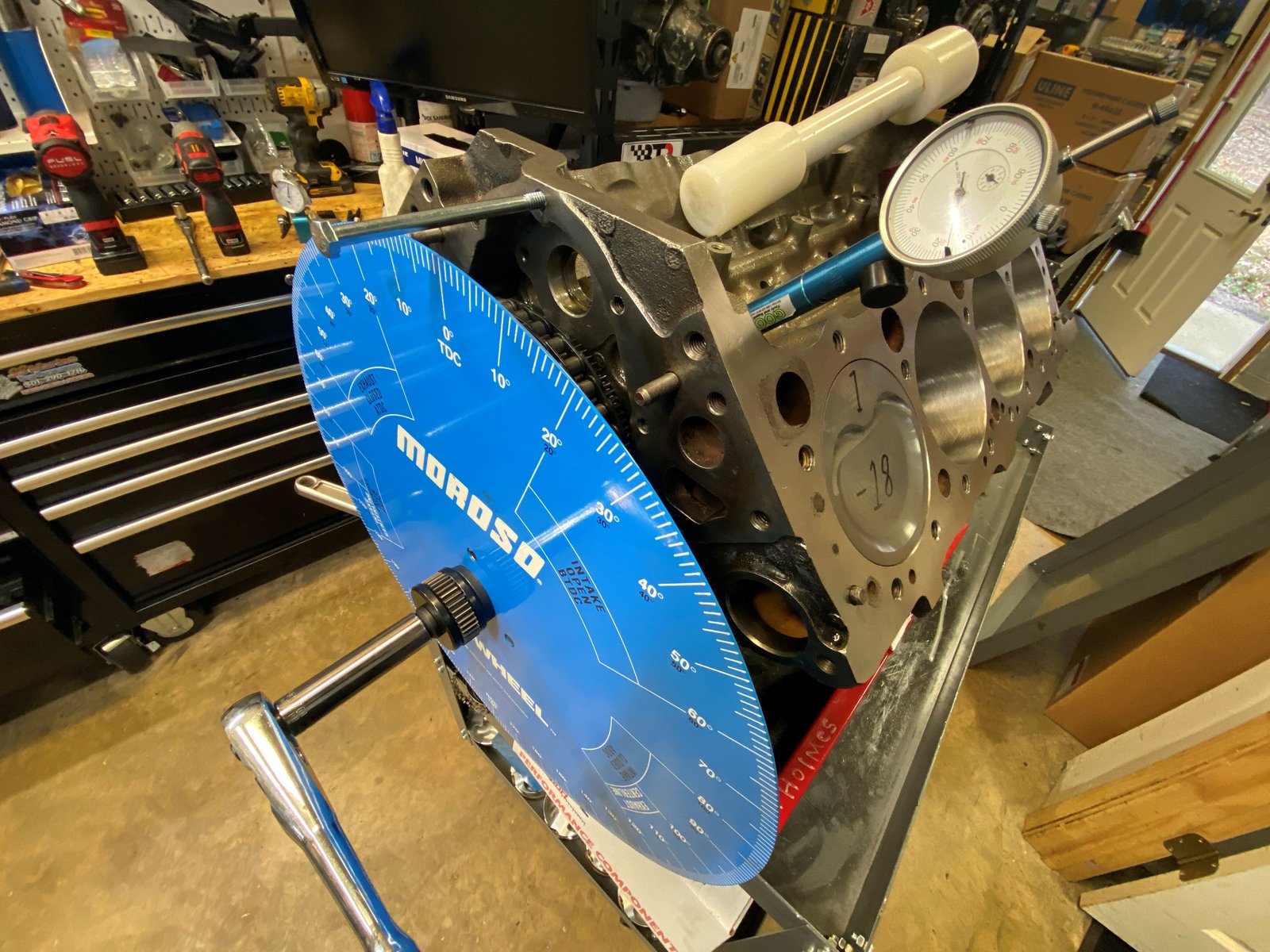
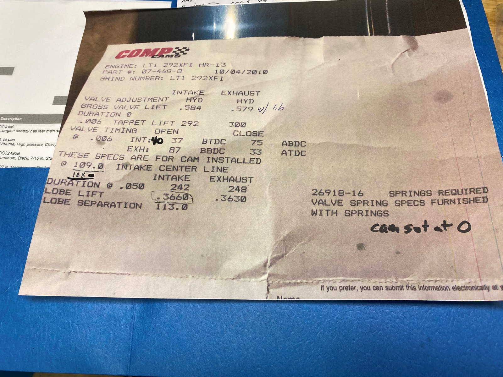
Here is the cam-card. Reasonable lift and duration.
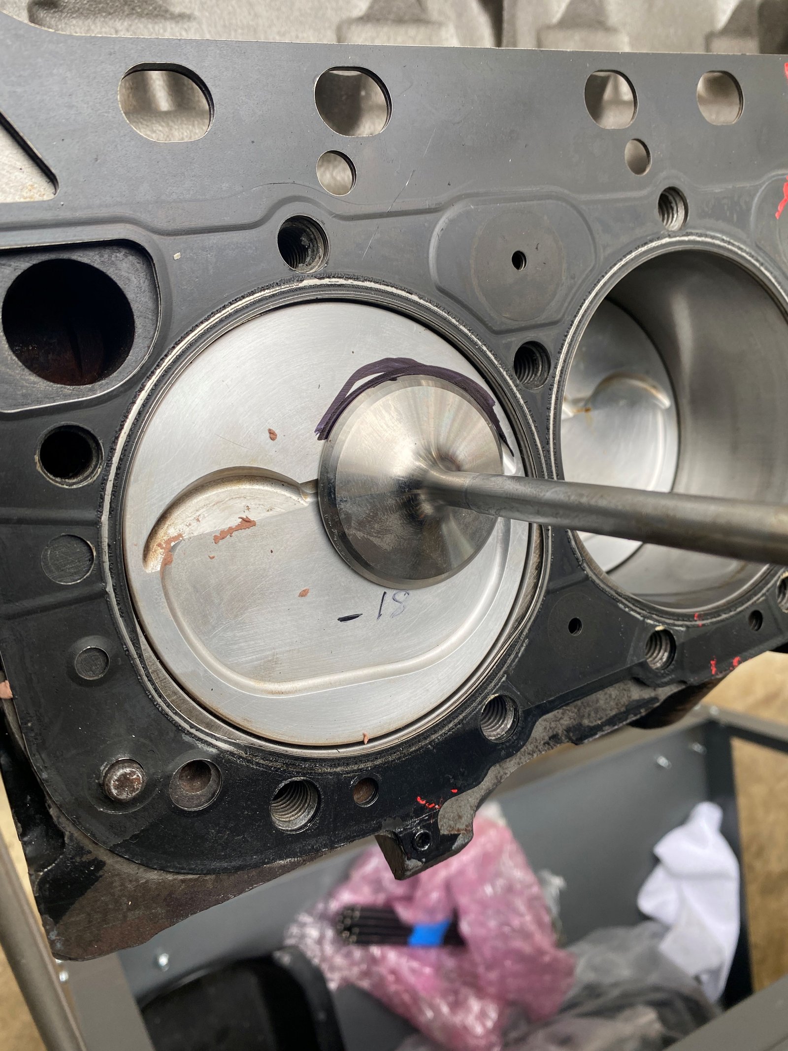
Checking how far the piston is in the hole.
Ended up with not the best results. The front is
.018" in the hole and the rear is .022" in the
hole. So the deck/block is not square.
The rotating assembly is quite hard to turn "by
hand/wrench". I think it's the rings or not enough
lube. The bores do not look good but this is easily fixed with
a hone.
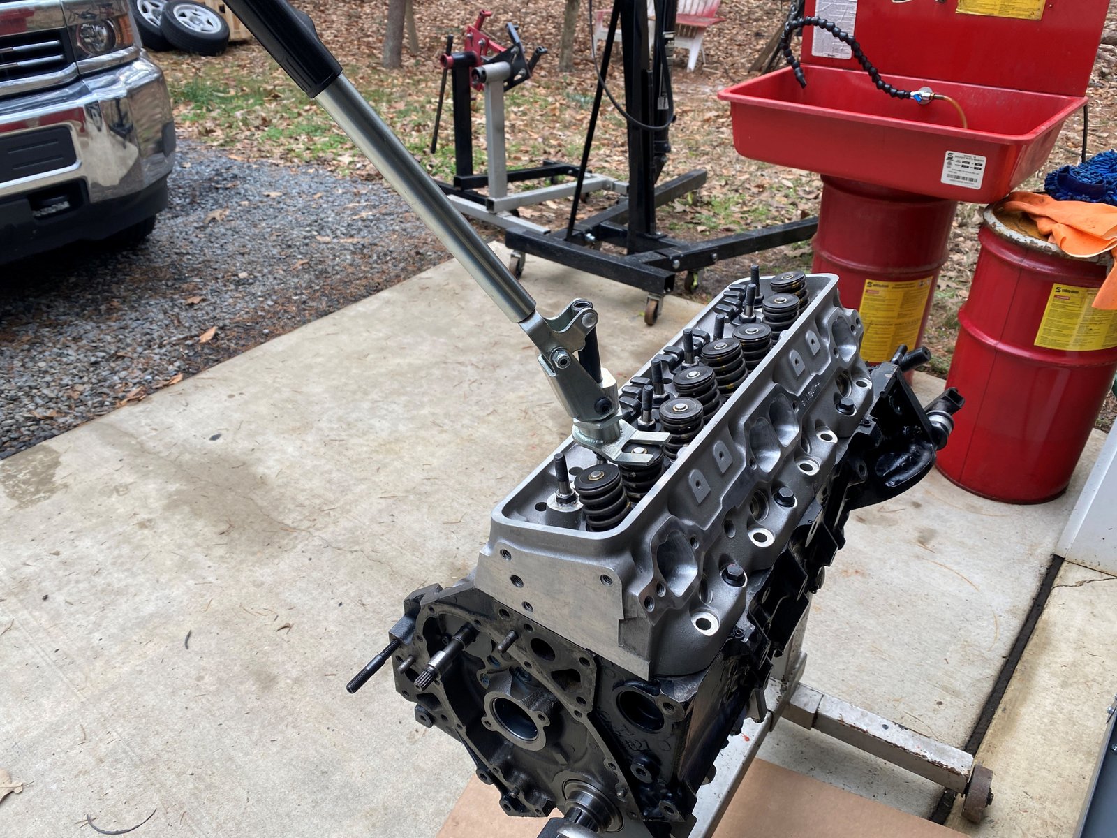
The heads are TFS Twisted Wedge and for some reason I did not
take detailed photos. Anyway here I am removing the intake
and exhaust valve of #1 cylinder. I want to make sure the
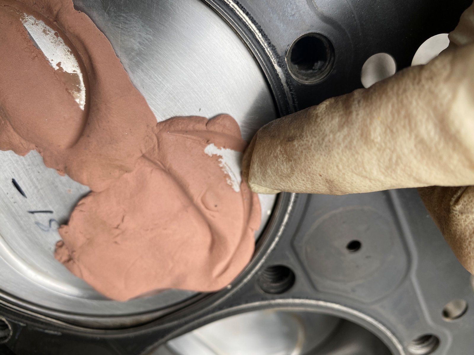
piston to valve clearance is ok. The pistons do not look
like they fit for these heads (at a glance). So I am going
to make clay impressions to verify.
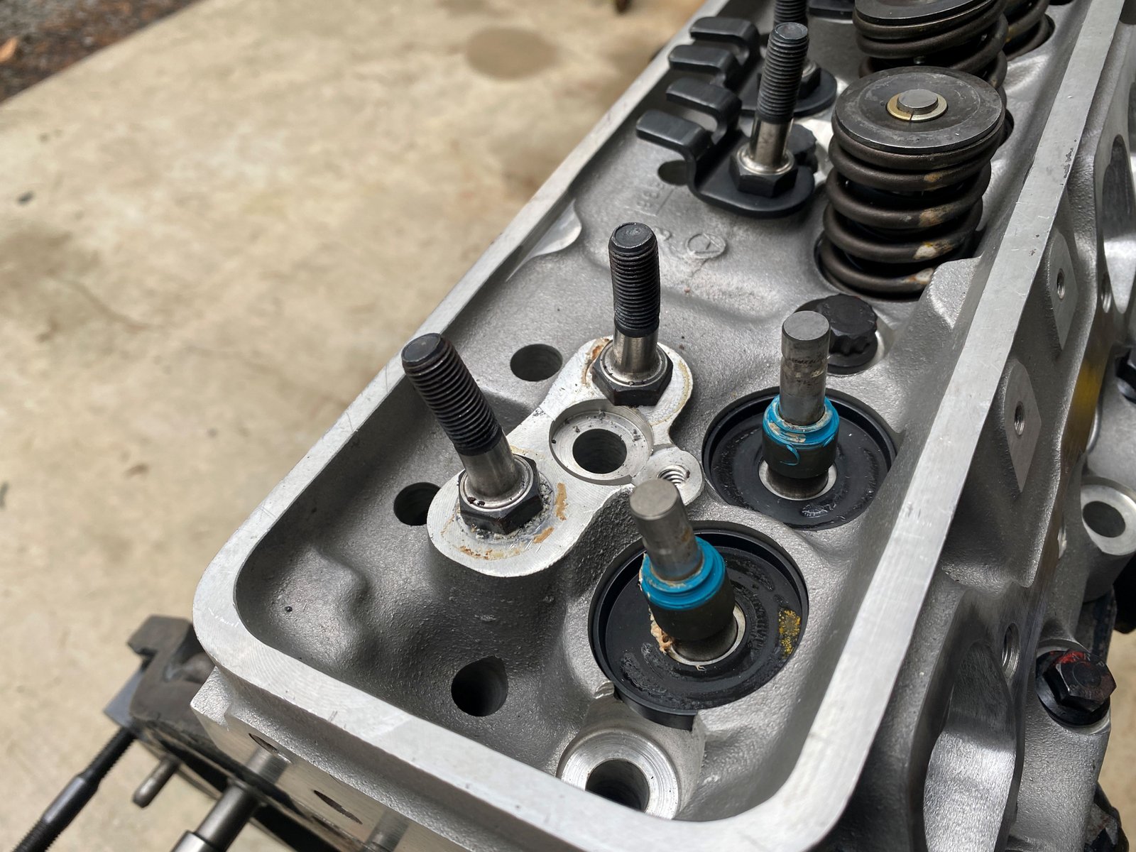
My valve spring compressor tool makes for easy spring removal.
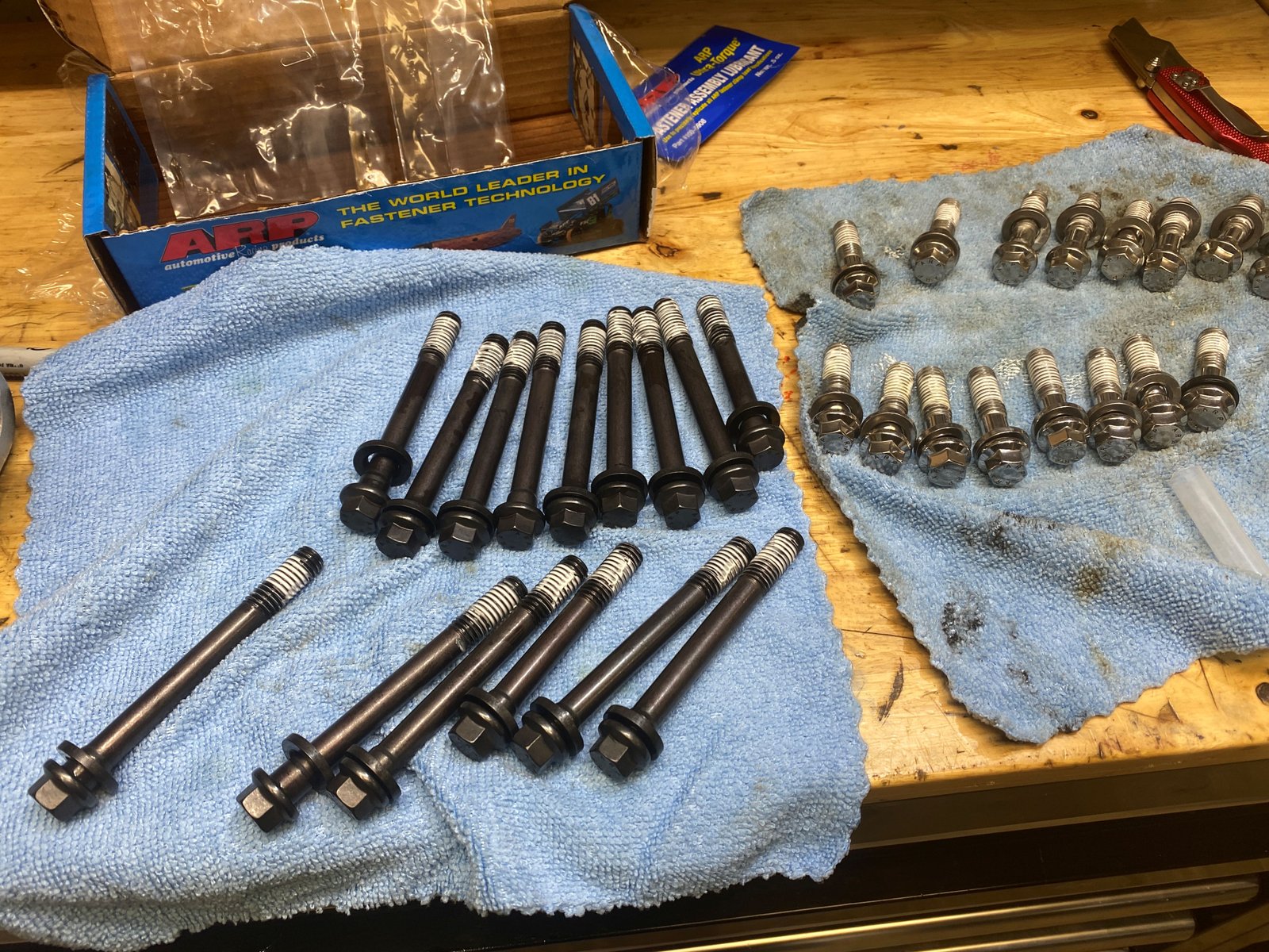
Well here is a good catch. While compressing the
spring..these thin and weak 3/8" rocker studs bent like wet
noodles. The heads need a good strong set of ARP 7/16"
rocker studs.
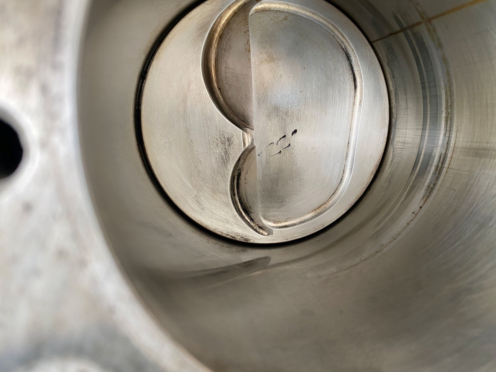
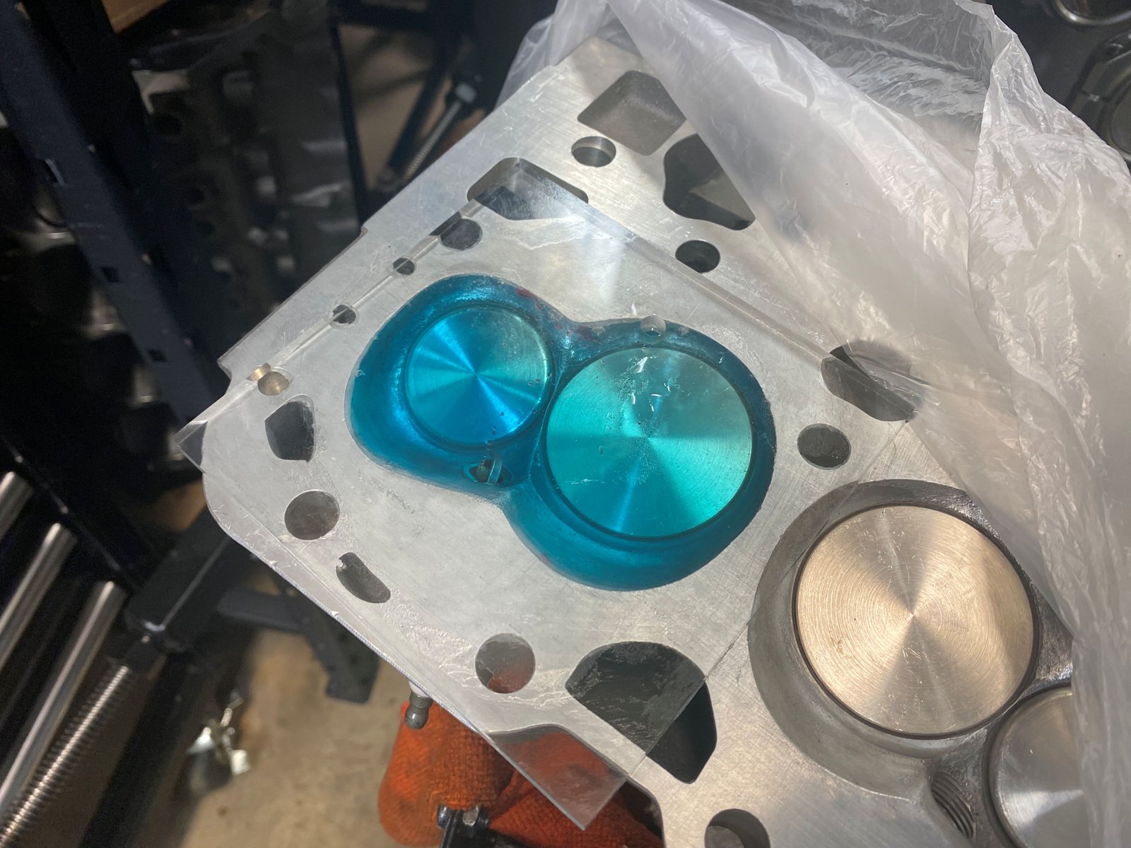
OK. Bad news. The heads have the intake valve at
13* and in a different position than the normal 23* intake
valve. The pistons did not look like
"custom". Here is the proof. The intake
valve does not fit into the valve relief. The exhaust valve
is fine and does fit into the valve relief.
This is where the valve actually needs to have piston
clearance.
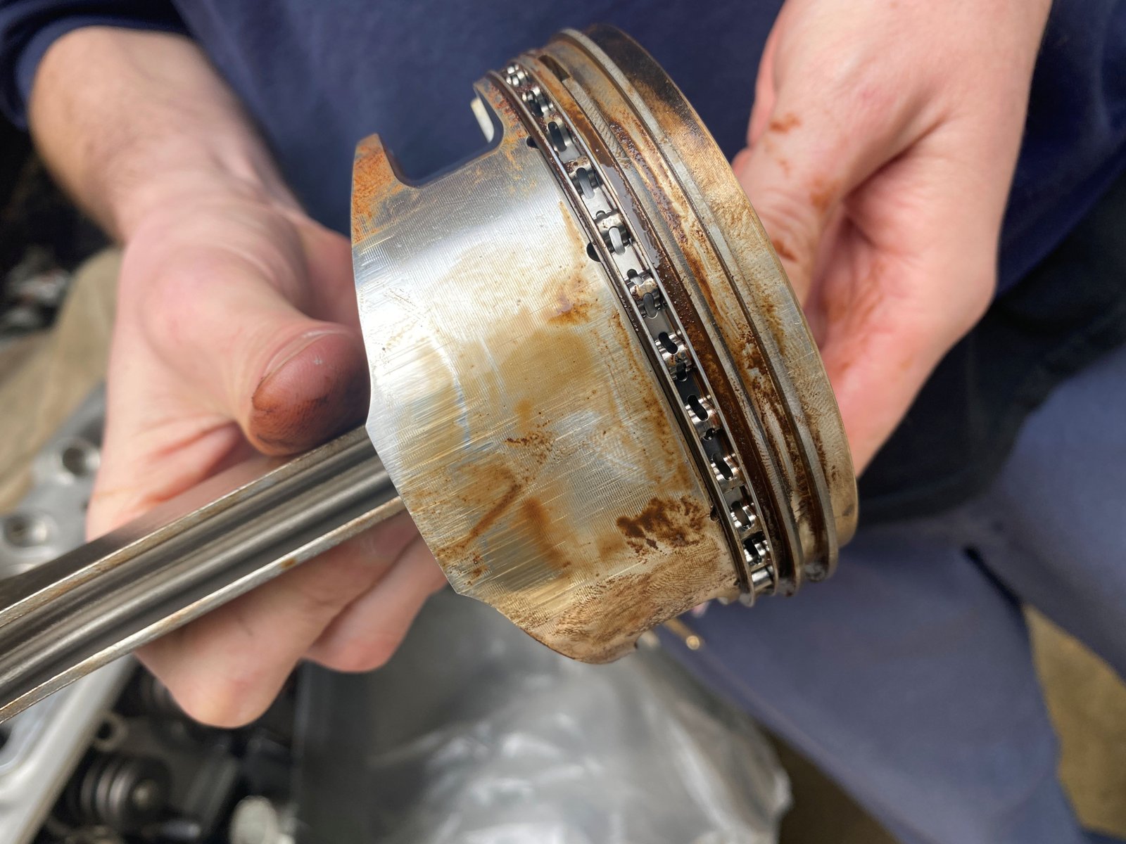
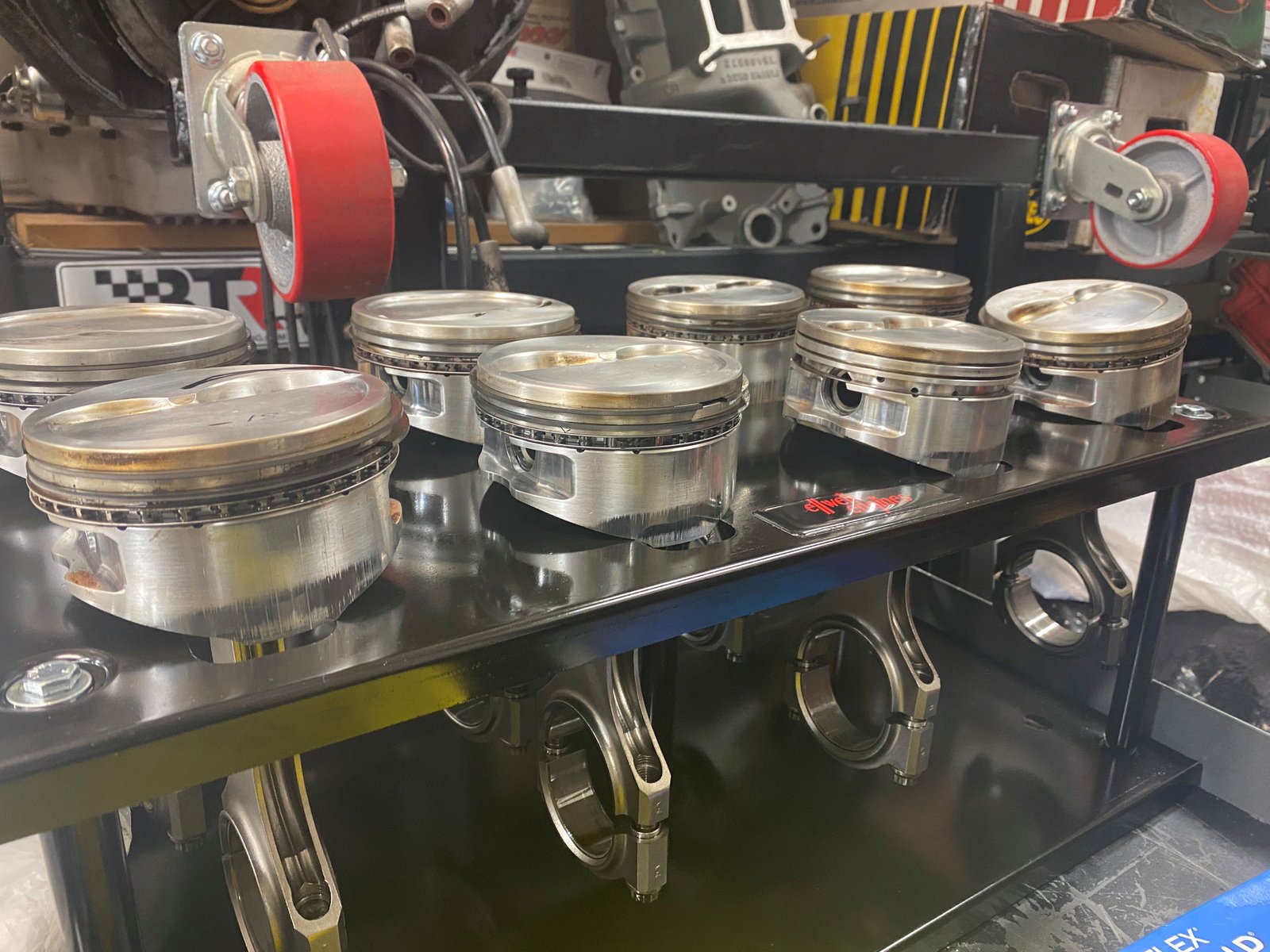
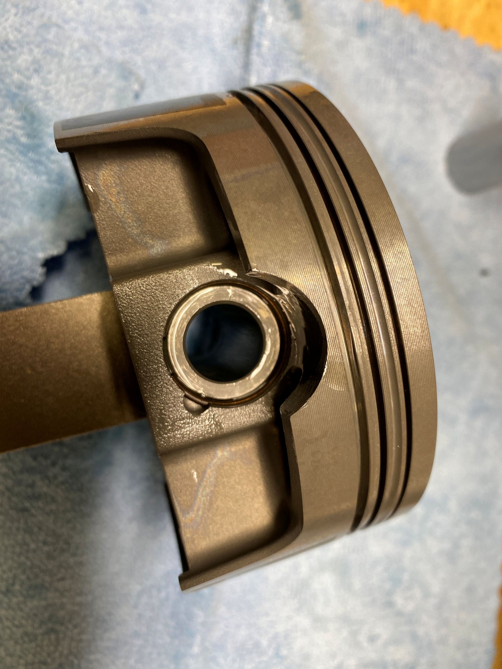
The pistons are grimy. Possibly this is just the cleaning
degreaser when the previous owner "cleaned" up the engine
for sale. But the piston skirts are very worn. They are
shrunk. The piston to cylinder wall clearance is .010"
and spec is .006"
Ring gap is 0.023" (but if you put the ring in a
4.030" gauge it is about .008" gap). The bore must
be more than 4.030". Turns out that the bores are a
very worn 4.035 and not at all in good shape. They can be
revived with a bore and deck plate hone to 4.040". The
pistons are really not usuaeble. the skirts are
shrunk. New 4.040" pistons are recommended.
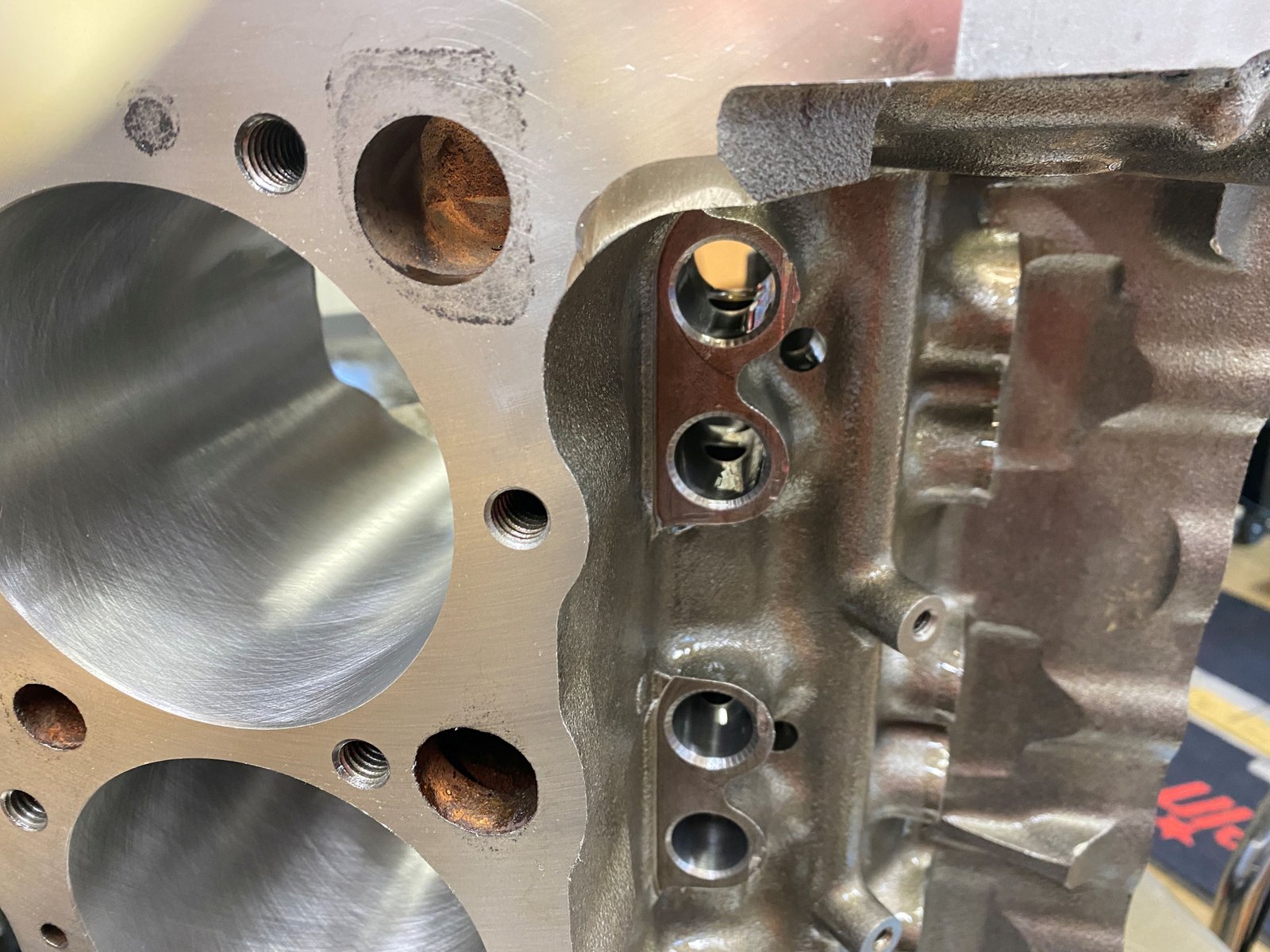
Not enough rod to block clearance. Needs a bit more
massaging here.
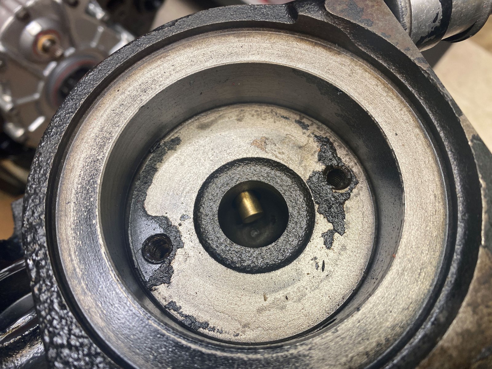
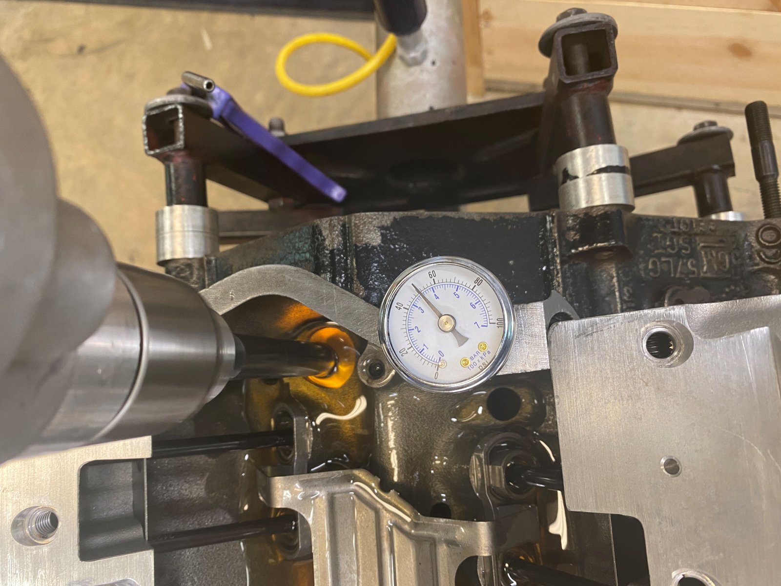
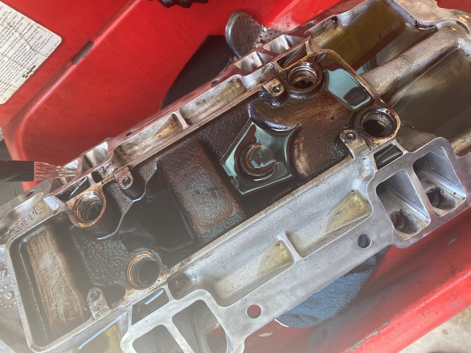
I took this photo to show the oil temp sender sticking into
the oil flow area. I would not put that temp sender in this
spot. It won't restrict flow though. Oil temp is best
taken in the oil pan.
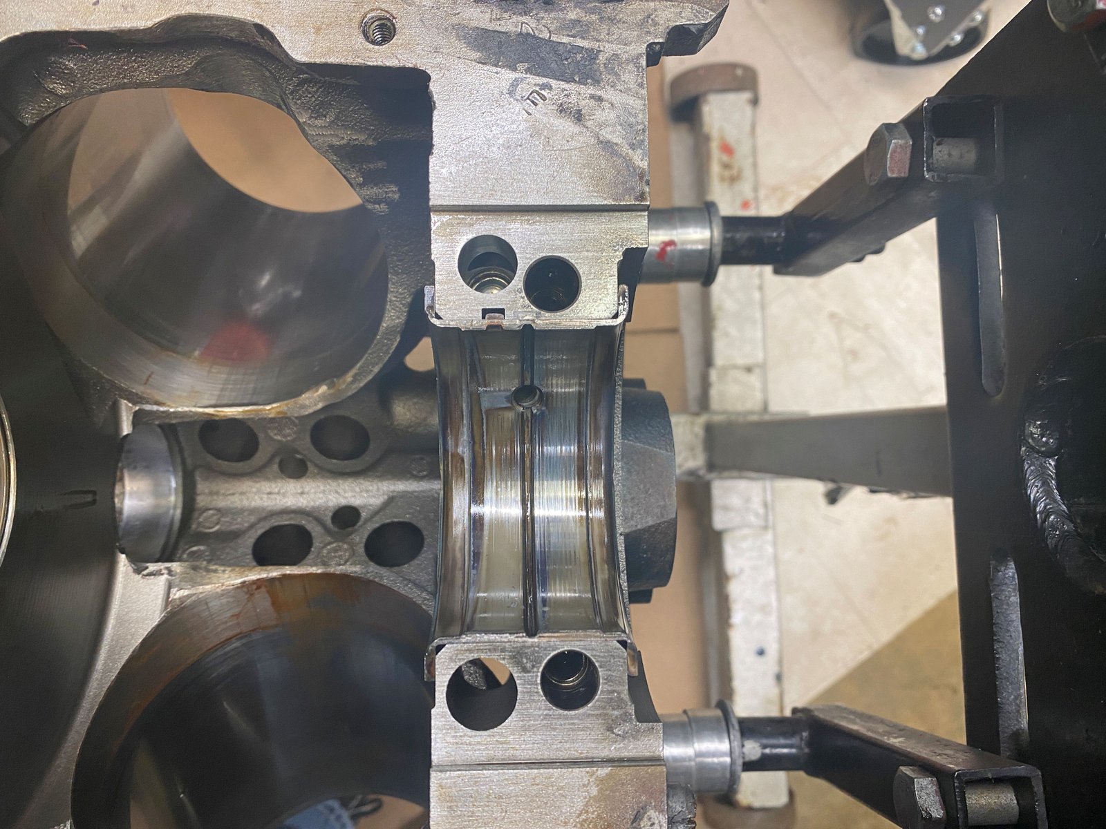
Main bearings are all pretty good.
It looks funny but is in good shape actually.
I took this photo to show the camshaft bearings. They
look like they are new. Maybe they are?
Recommend:
1. Block to be bored and honed to
4.040" over
2. New 4.040" over pistons.
3. New balance
4. Square deck the block
5. 7/16" rocker studs
6. New piston will also need to be "fly-cut" to
fit the twisted wedge intake valve---Clinton Machine can do that.
Piston skirts do not look good.
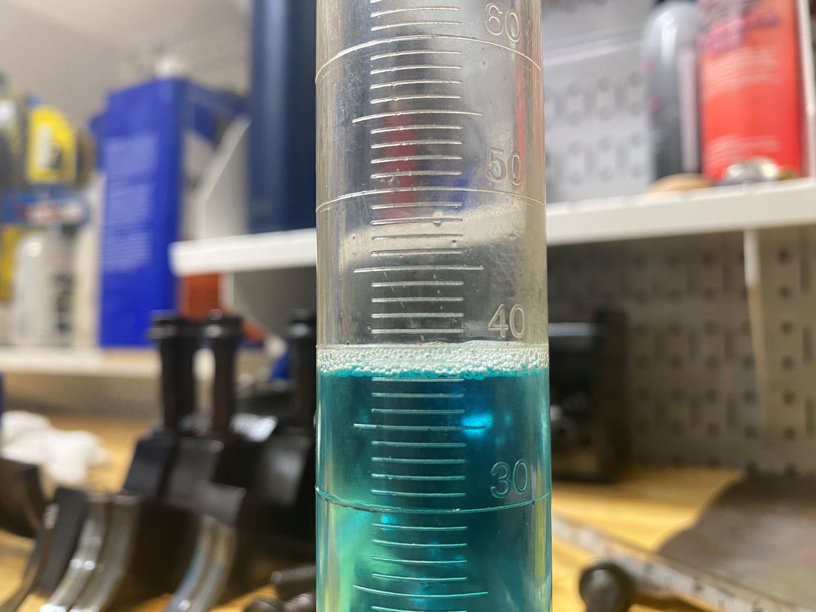
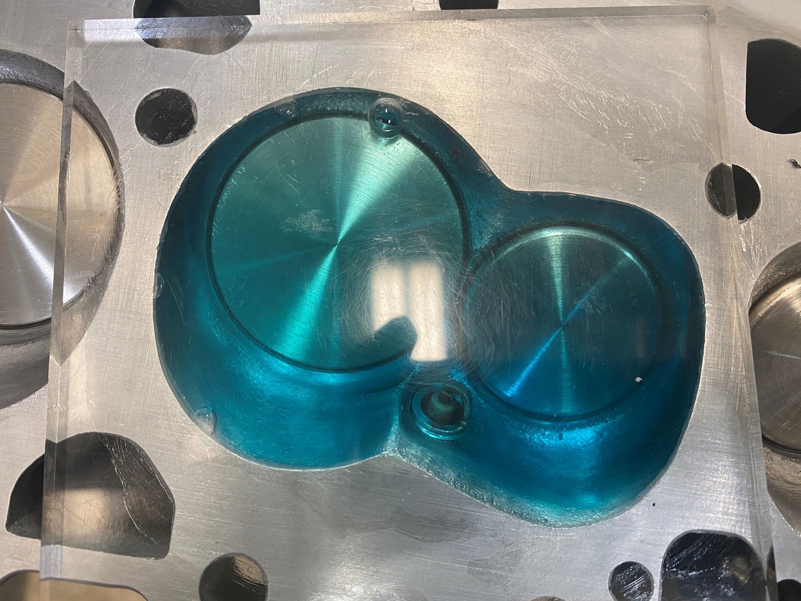
Need to know the cc of the combustion chamber prior to
ordering pistons. If large chamber then I could order a flat top
piston and if small to medium size then a dish is required.
A few tiny bubble left but pretty full.
Looks like 62 cc (100cc -38cc = 62cc).
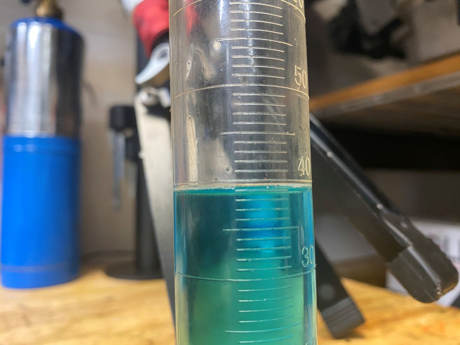
Now a 2nd measurement in a different chamber. Some bubbles
but full enough.
This shows 61 cc and so I'll call it 61 to 62 cc for the rest
of them. A Mahle -18 cc piston will give 10.13
compression ratio if using a .027" MLS gasket (6cc).
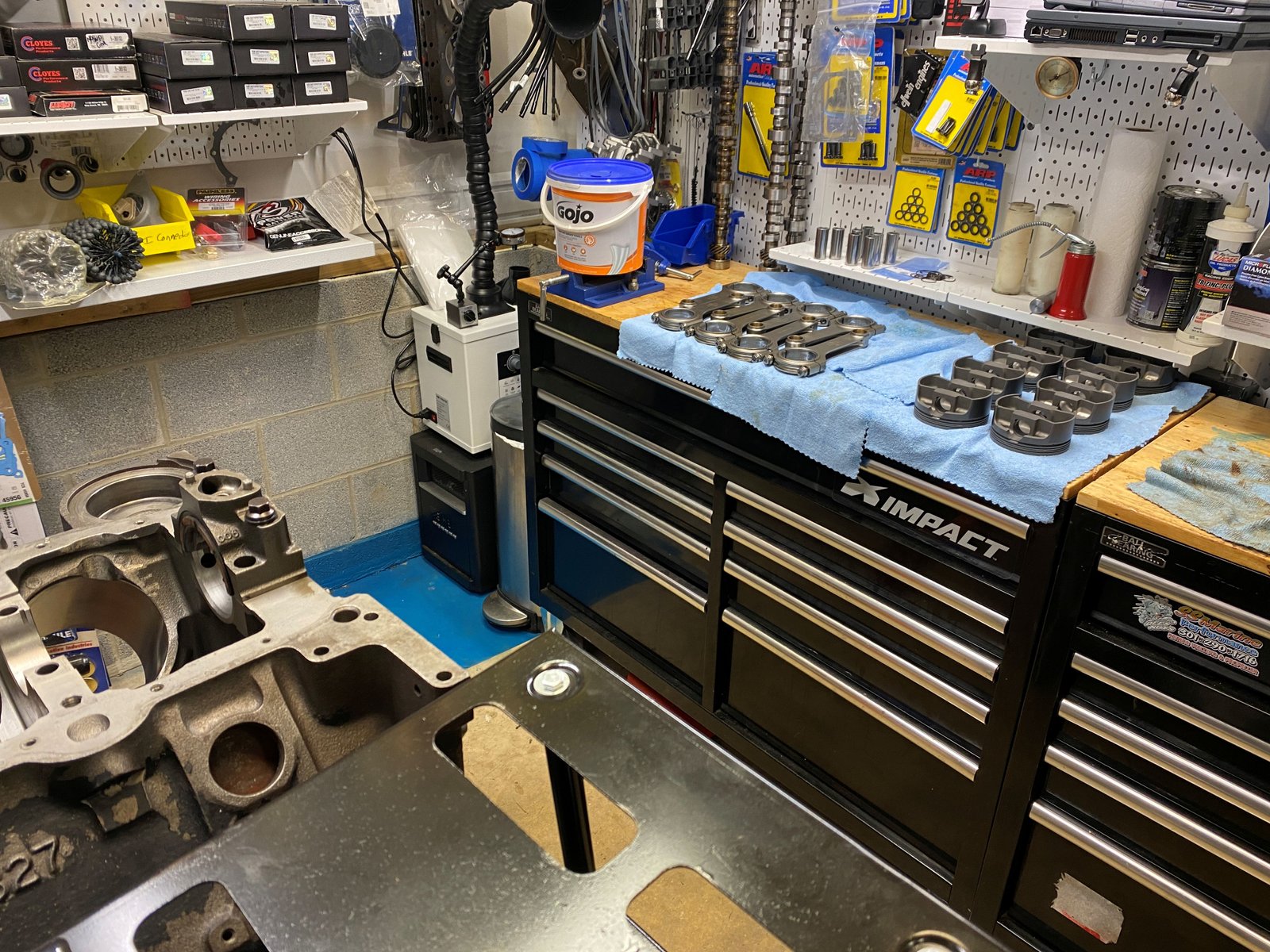
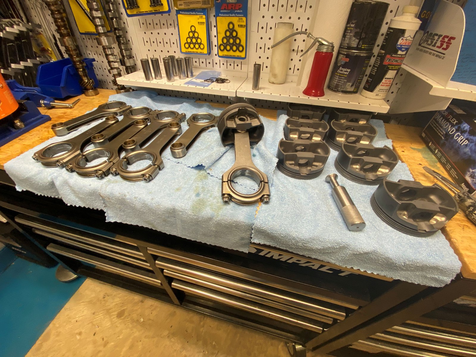
The crankshaft has been balanced and the block has returned from the machine
shop. The block is at 4.041" bore size and it has been square
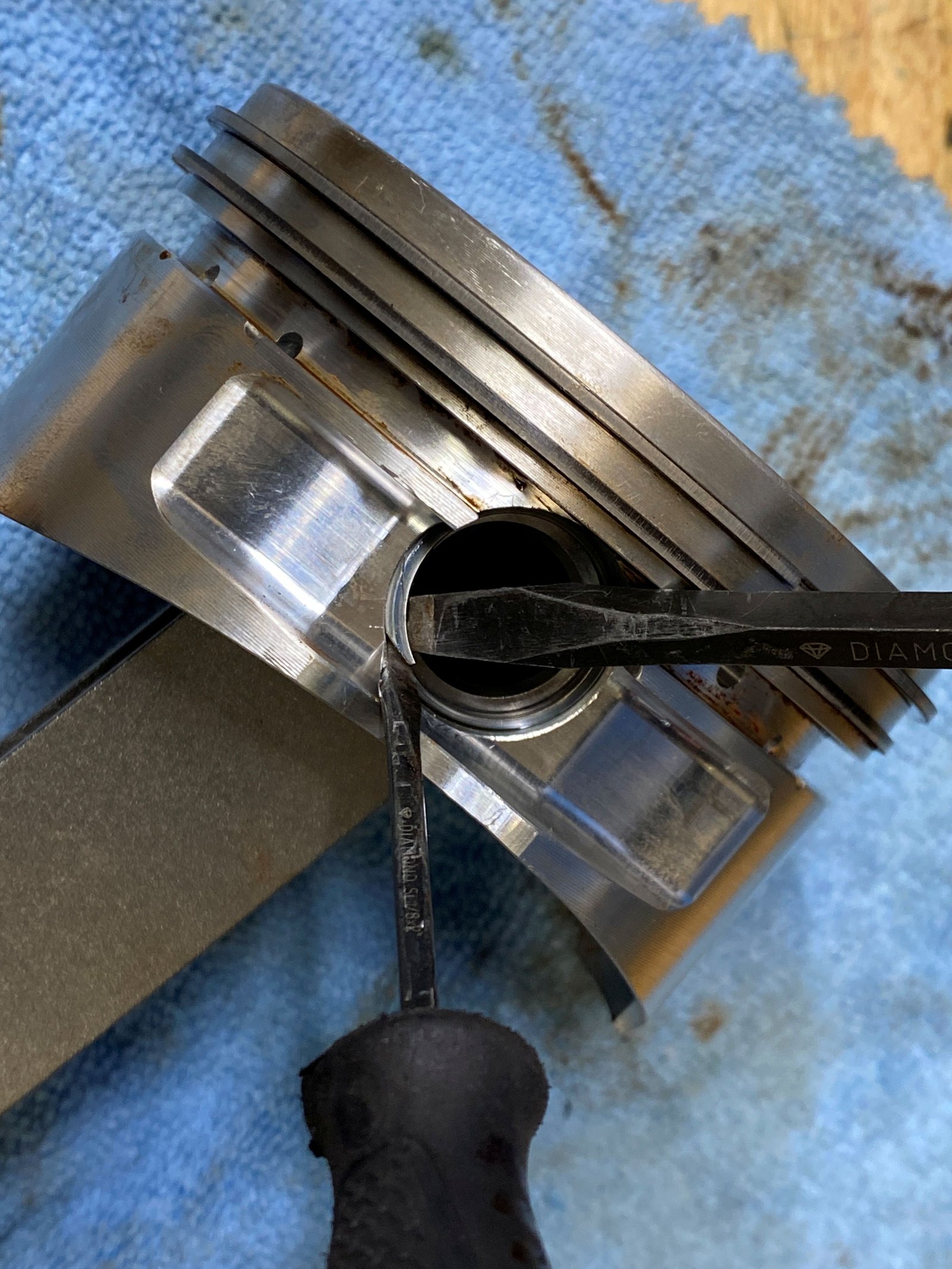
decked. Now it's time to dismount the old pistons from the rods and
assemble the new Mahle pistons to the rods. To the right is how I take out
the spiro-lox.
The new pistons do not use spiro-lox. Mahle pistons use wire locks.
The are very reliable and 1g lighter than spiro-lox.
The old cam bearings were in pretty good shape but I am reluctant to re-install
cam bearings. New cam bearings are cheap $30 insurance.
The camshaft core serial numbers match the cam card.
I cleaned the preservative oil off of the camshaft.
Before I go any further the piston to valve clearance needs to be
checked. Most likely there will be no need to
"fly-cut" the piston tops to match the canted intake
valve. To check piston-to-valve clearance I have the full
rotating assembly installed (only #1 rod/piston). I
installed the cylinder head with a few head studs/bolts and a set
of lifters are installed at #1 intake/exhaust. The
7.300" pushrods supplied by the owner seem to fit quite
well. Valve checking springs are installed.
When checking visually with borescope it was obvious that there is plenty of
piston to valve clearance. The exhaust valve is not canted and is in the
normal 23* location but the intake valve is more toward the center of the piston
and it does not match the 23* valve relief. Not a problem here because the
intake has a mile of clearance. I did notice that the lifters were still
collapsing when trying to open the valve even with checking springs and so I put
in a set of mechanical lifters and clearance was still good. It was at
least .200" for both intake and exhast.
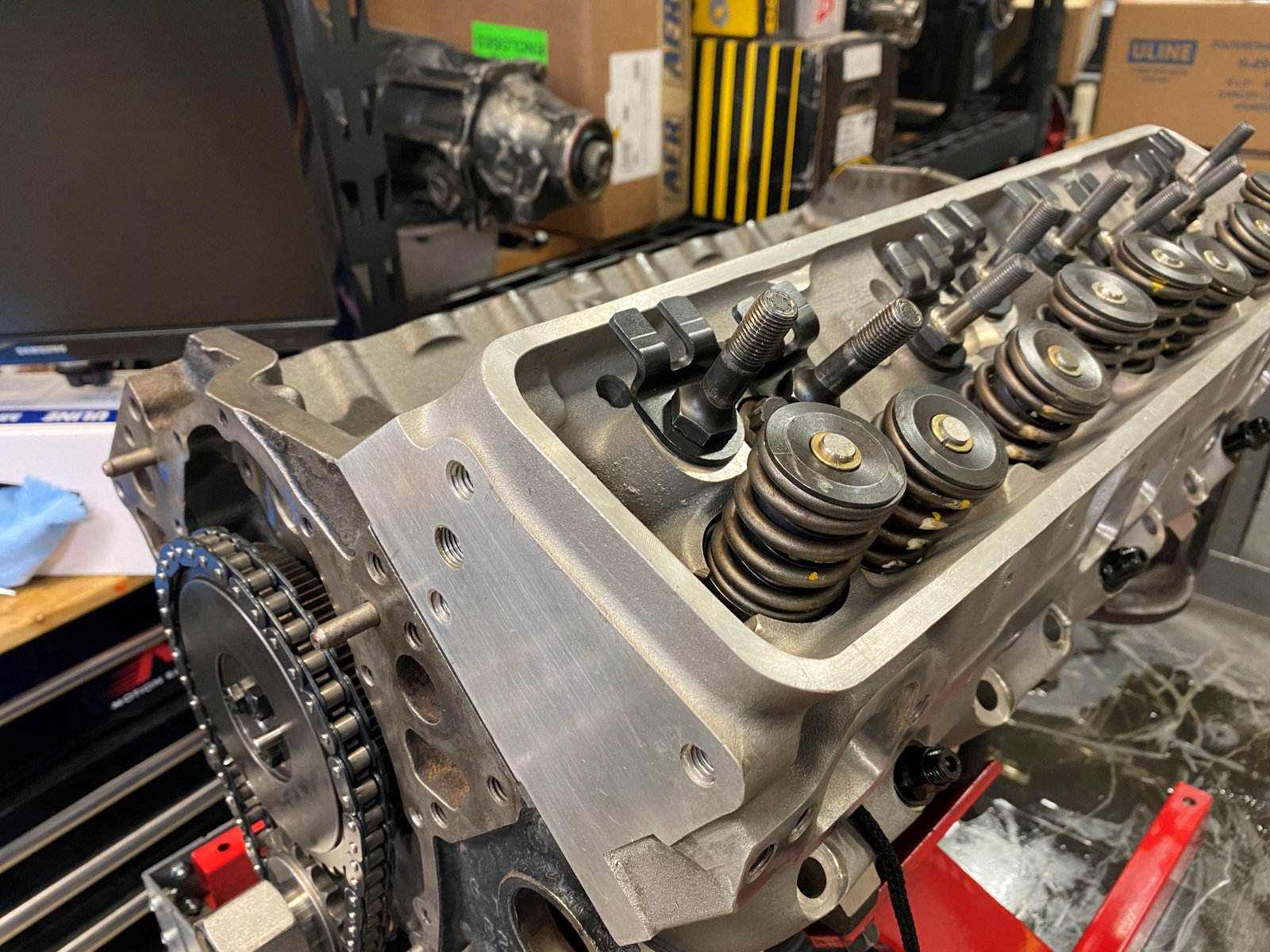
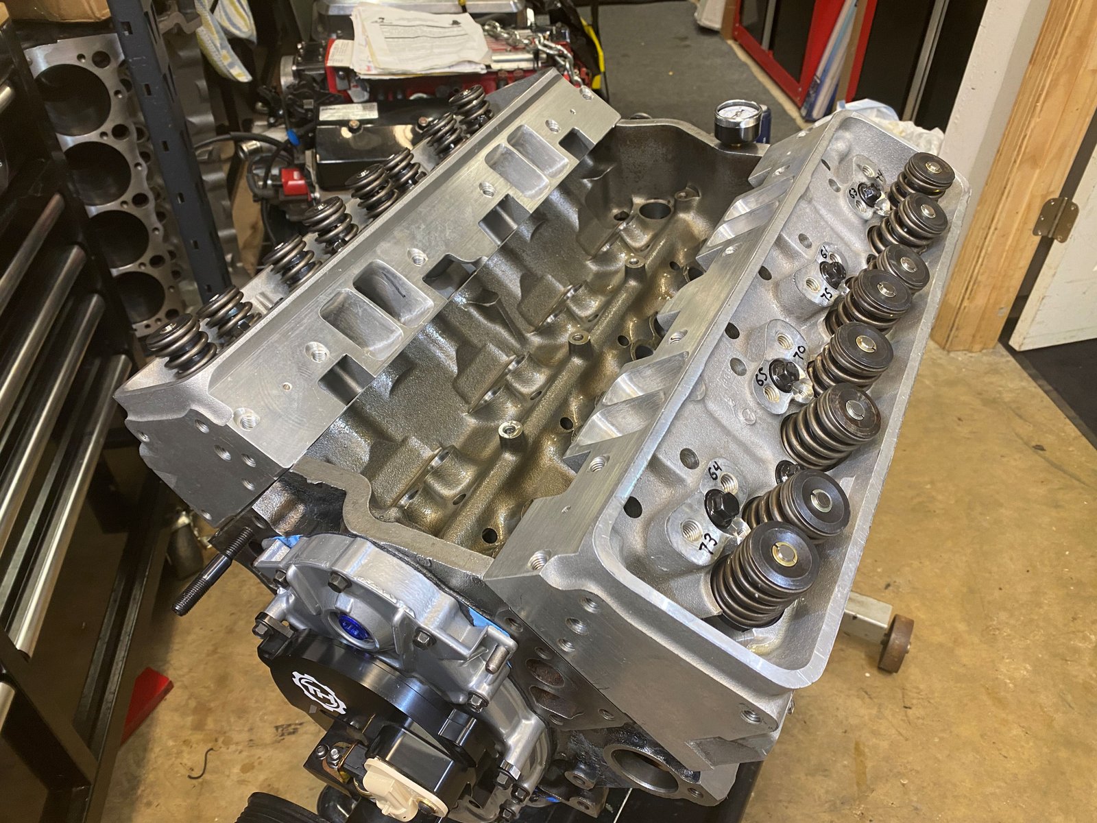
Here is a view of the valve springs re-installed. The heads are getting
the 7/16" rocker studs to replace the 3/8".
Now the mains are installed and the bearing clearance is .003 at #1,#2,#3,#4 and
the rear cap is .004"
Next on the assembly agenda is to do the final cleaning and prep of the block
and then fully assemble the engine.
Final block cleaning: 1st: Make sure to finish the preparation fine
details. I tapped the front galleys for threaded plugs....
...also honed the lifter bores.
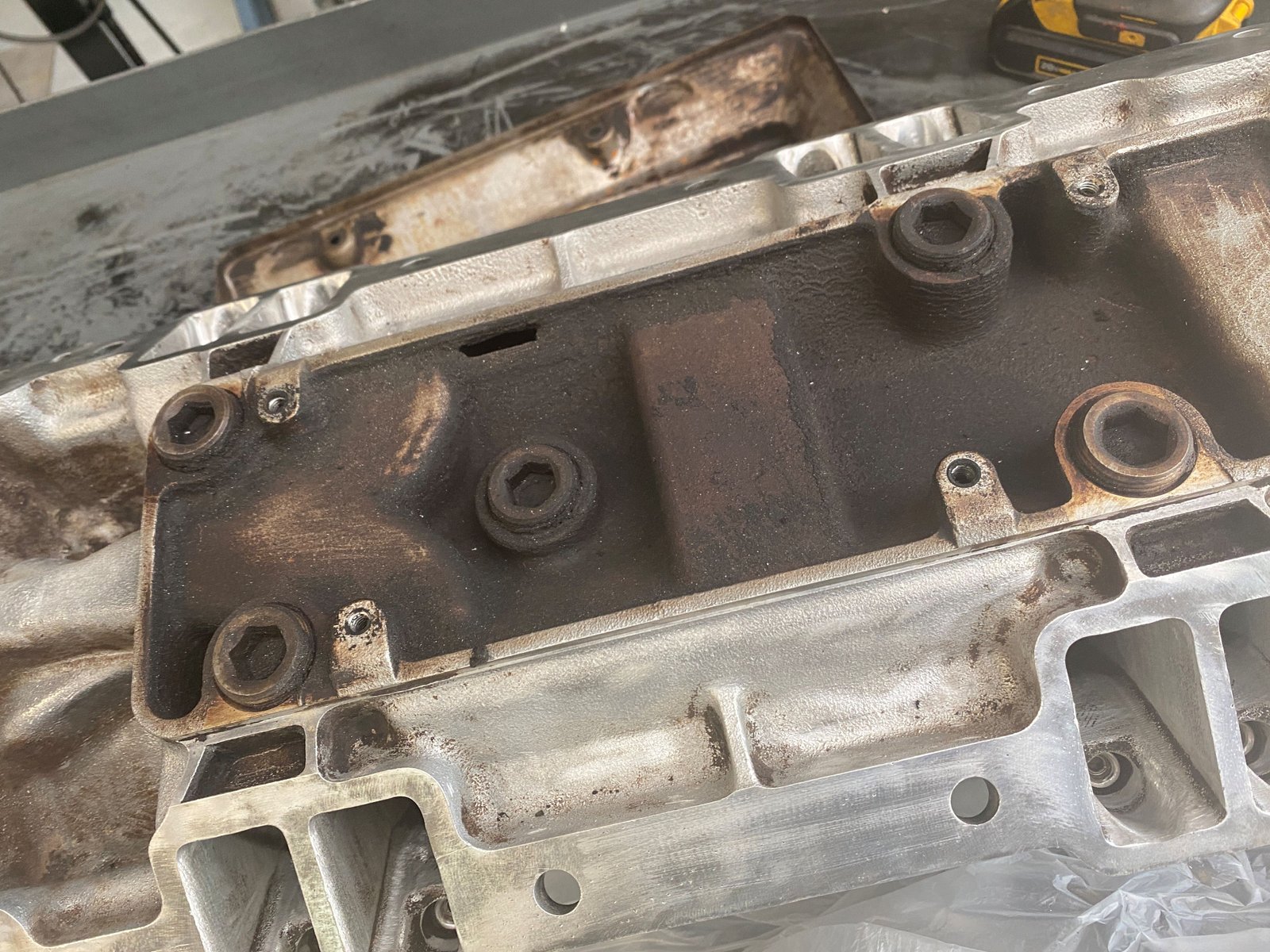
And made an oil drain back path at the front-right side of the drivers side head
deck. Then washed and washed and oiled and oiled.
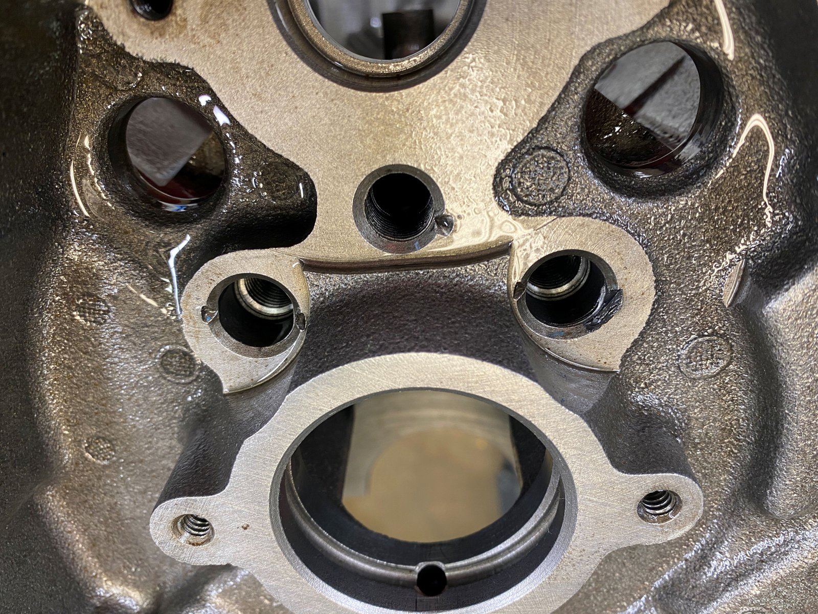
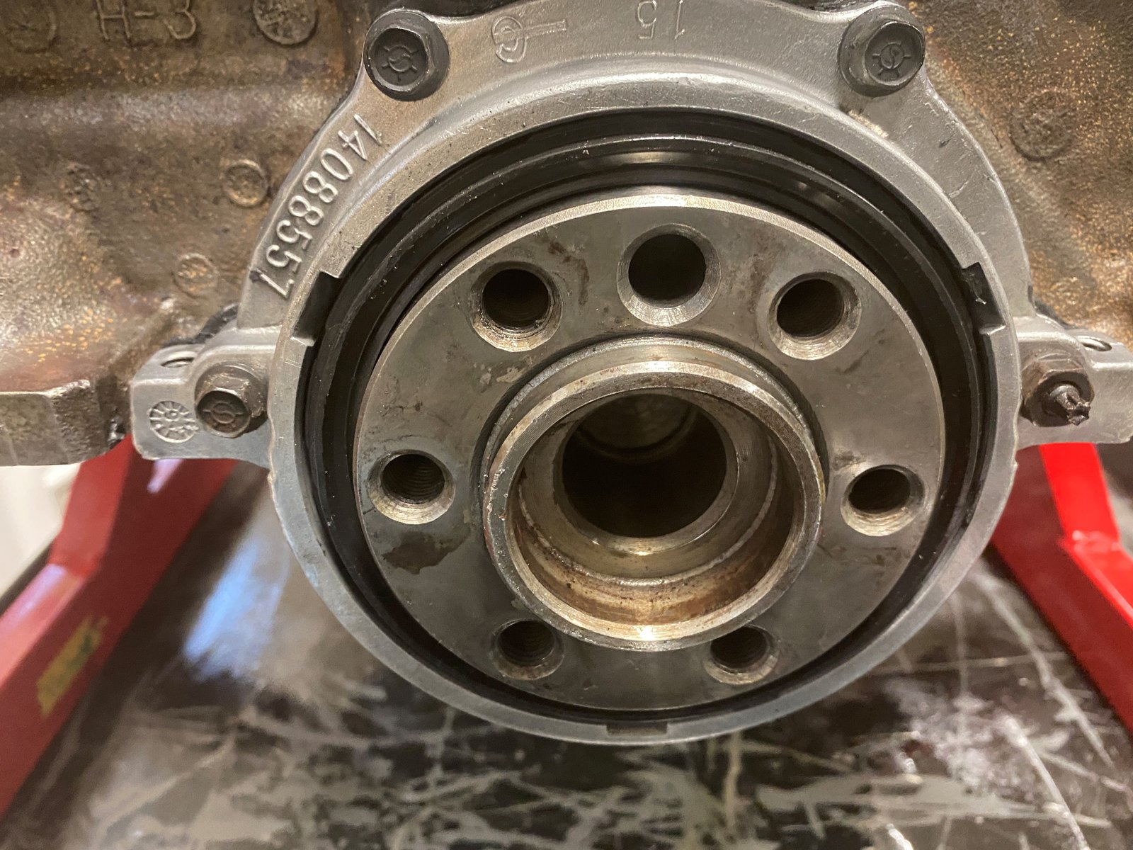
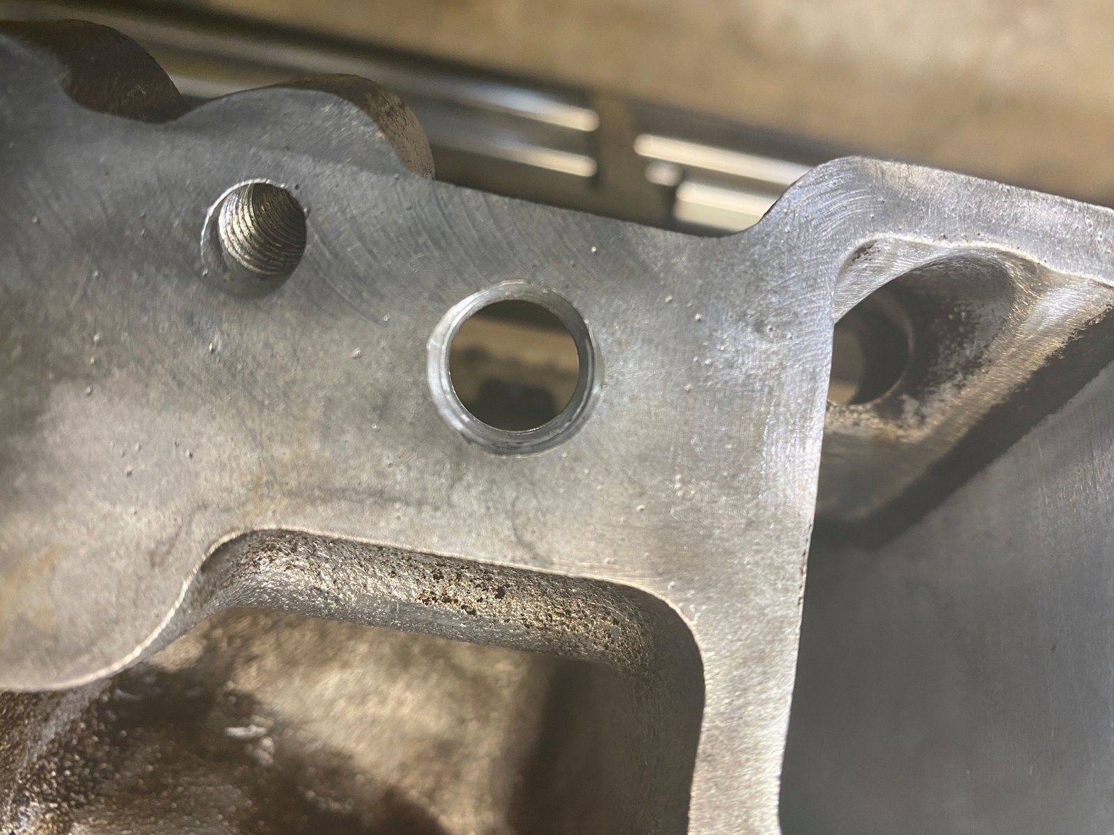
Also made the rear main oil supply hole fit the bearing. It is smooth with
no sharp edges although you can see one tiny slip of the drill on the
bearing. Also in this photo is the main cap oil galley plug.
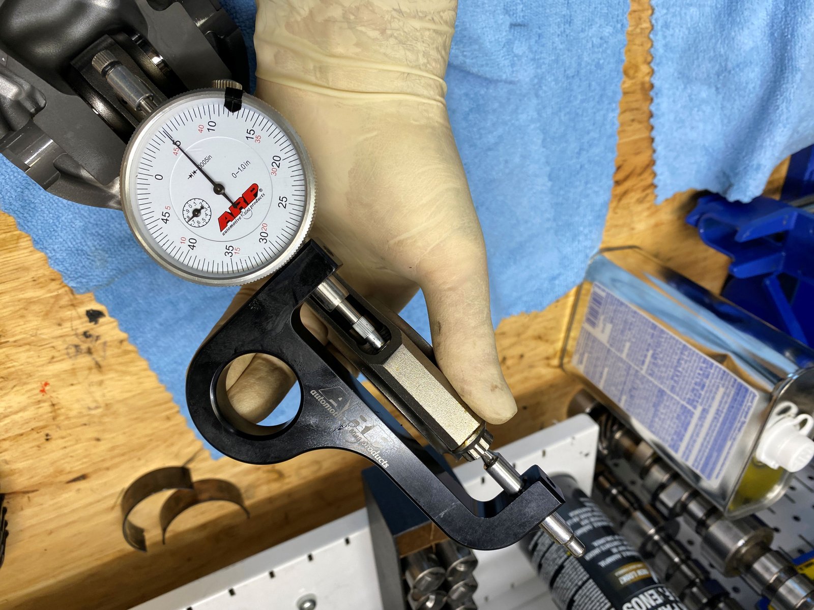
The bolts were stretched to .005" and that took 65 ft-lb with my torque
wrench.
All rod bearings were .0020" to .0024" with the ultra premium
King CR 807XPN bearing.
The old rod bearings were in OK shape and could probably be re-used but why not
start with a new set?
Cam degree: 108 Intake Center Line at the zero crank sprocket
position. Cam card shows that this is 1 deg retarded. When I put it
to the 2 deg advanced position I get 111.5 ICL and I think that is too advanced.
Here are my notes on the cam card for future reference. 108 installed ICL
on a 109 cam card.
Rings gapped per Mahle spec for forced induction up to 15 psi. This is
.025" top ring and .020" 2nd ring.
Installed 1, 2, 3, 4 piston/rod combos and at #4 I have a "bump"
sound. That is probably the rod hitting the cam. Easy fix but
I'll work on that another day. It's 6:30pm and time to watch Big Bang
Theory with my wife.
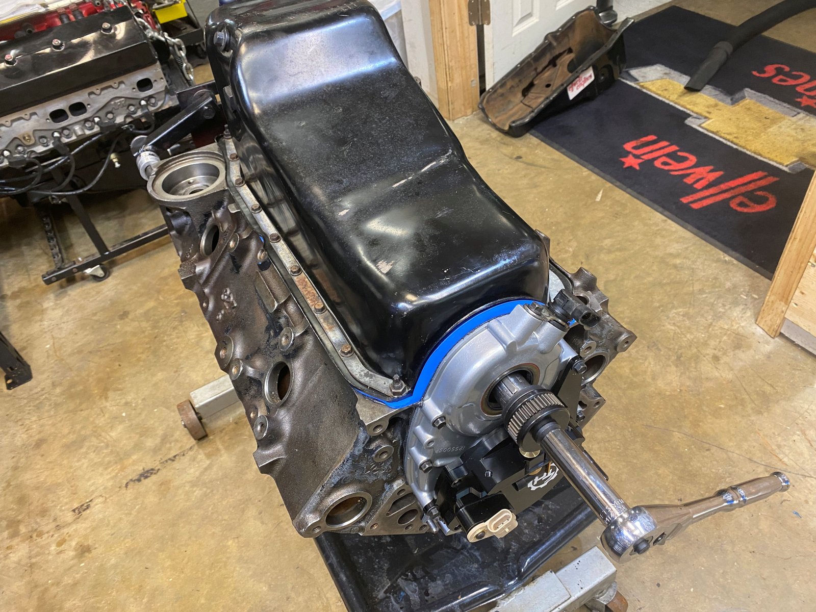
I need to put the engine on a traditional engine stand and so let's take the
opportunity to put on the rear main seal housing and then the seal. I make
sure to center the seal housing very carefully.
Now to address the rods bumping the cam. I believe it is #1 rod, (or
#2). Hard to tell which. I clearanced #1 and washed it up in the
parts cleaner....turns out #2 was bumping. Fixed #2 rod shoulder and no
more clearance trouble. The rest of the rods cleared the cam with no extra
effort.
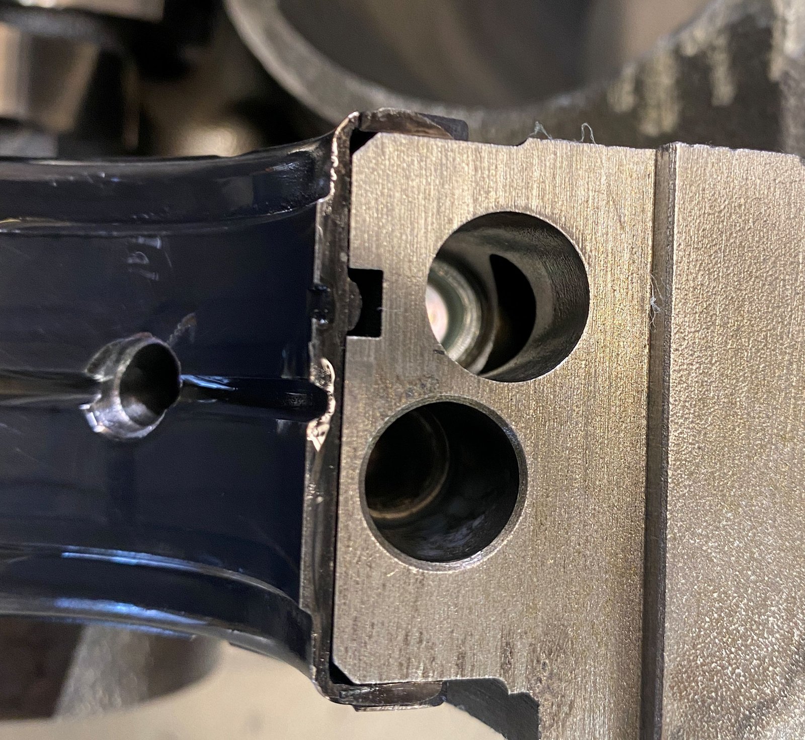
Good thing I added a little more clearance at the bottom of the block while I
was doing the last minute prep before final cleaning. The rod bolts are
very close. Just enough clearance.
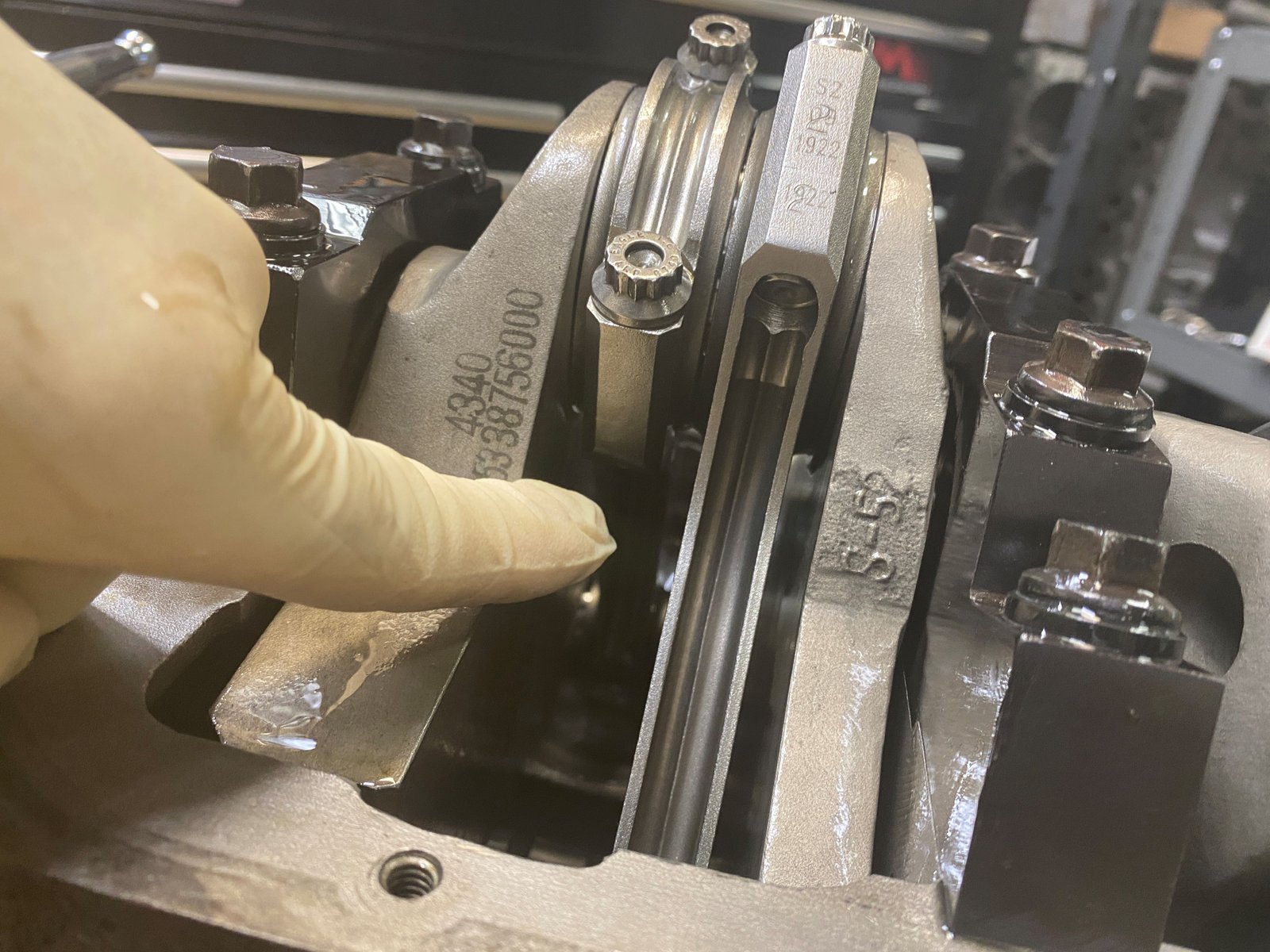
All rod bolts torqued to 65ft-lb and the rod side clearance is .025"
Eagle rods are always excessive on the side clearance especially mixed with an
Eagle crankshaft.
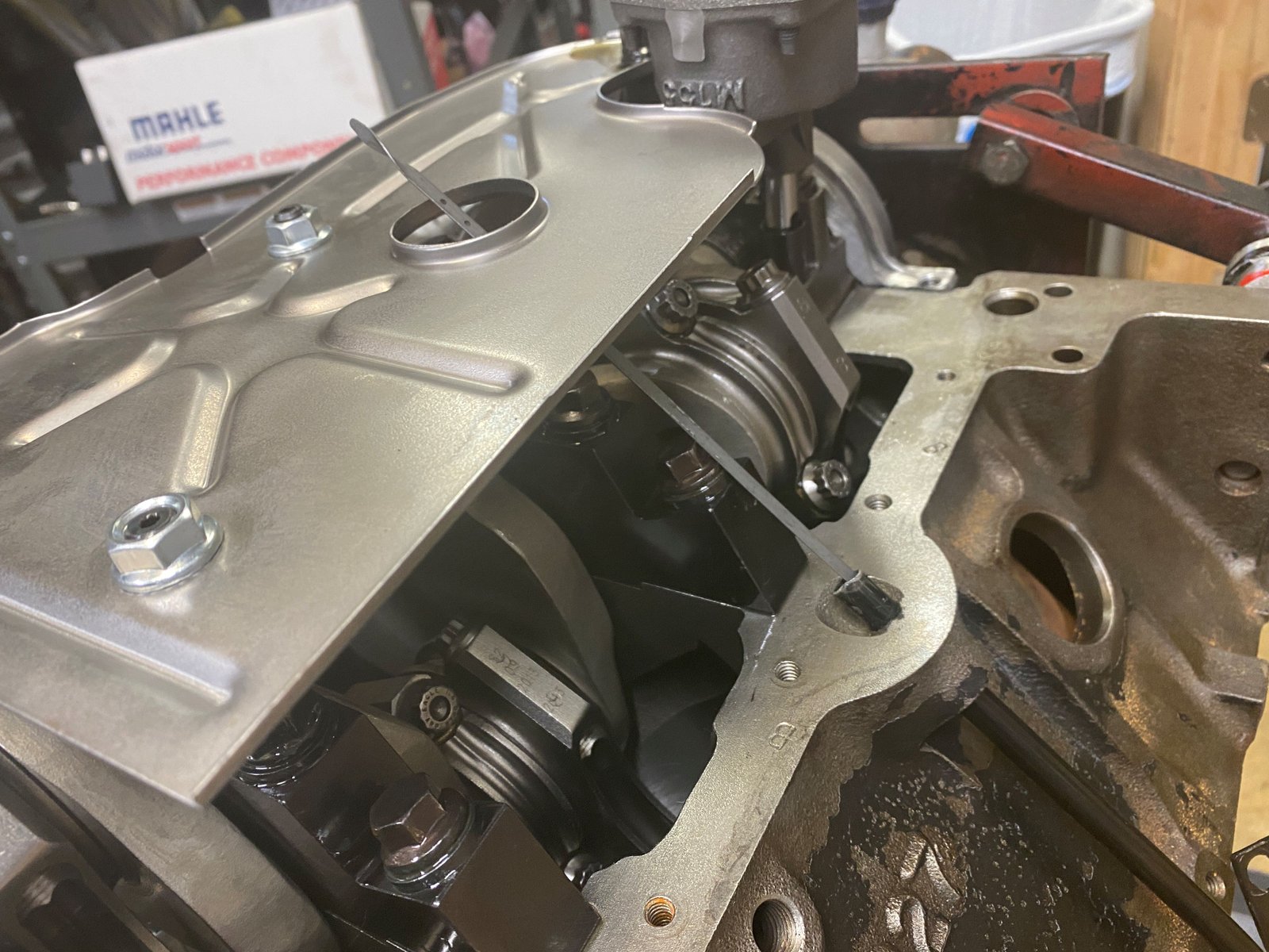
Added main studs for the windage tray and installed a brand new GM tray.
Minor massaging (bending) is required to allow the rods to clear. The oil
pump is a Melling M155.
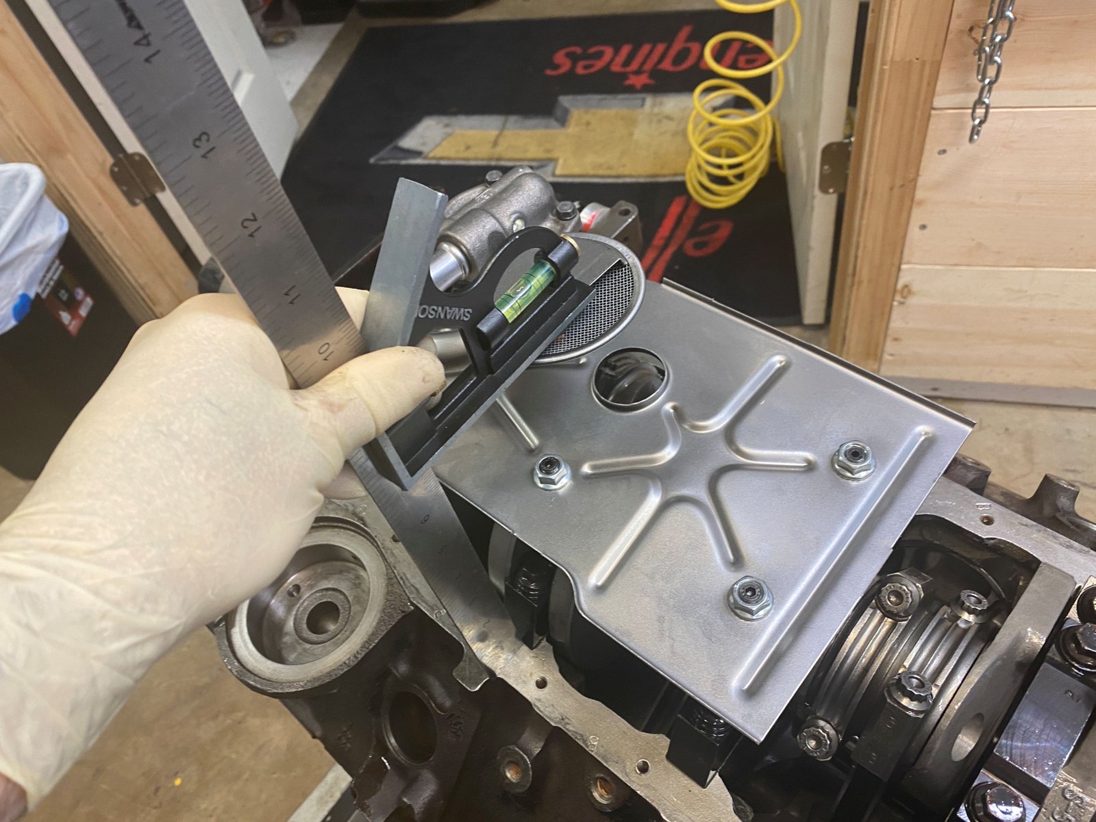
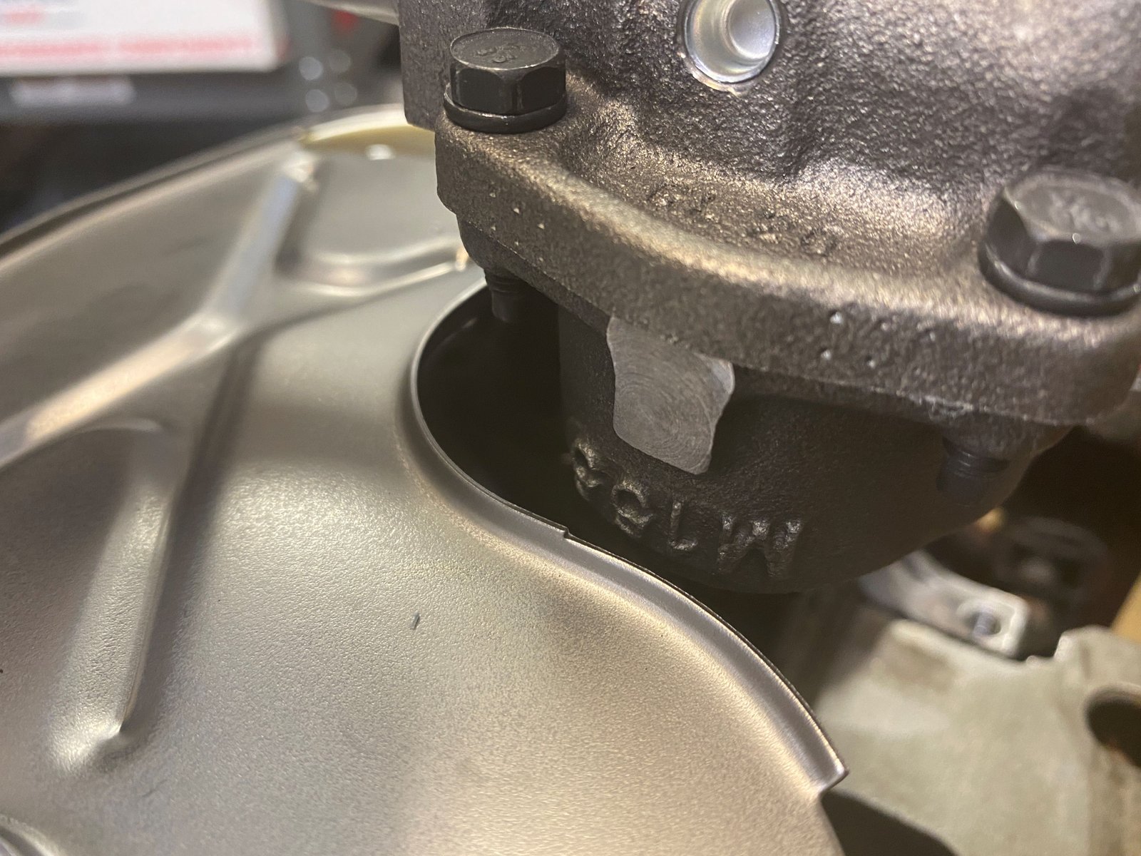
A dipstick tube needs to be shortened so as not to bump into the main cap.
The oil pump pickup is pressed in and I have it at 7.25" with no
gasket. That gives 1/4 to 1/2" clearance to the bottom of the pan.
M155 oil pump
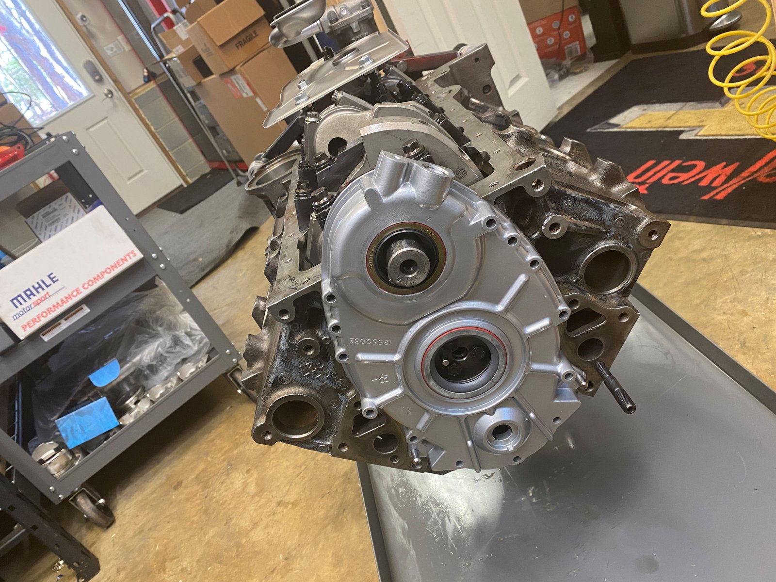
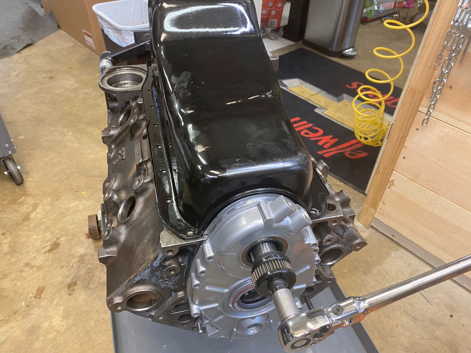
Refurbished 1996 timing cover.
Oil pan mockup. I want to see if rods bump.
The usual spot at #1/#2 rod. I always bend this area out with a hammer,
(on a stock pan).
After bolting the oil pan down there were numerous rod bolts hitting the
pan.
The solution was to clearance 4 of the rod bolts as shown here.
This is another rod bolt that hit the pan and was clearanced.
Good fit now.
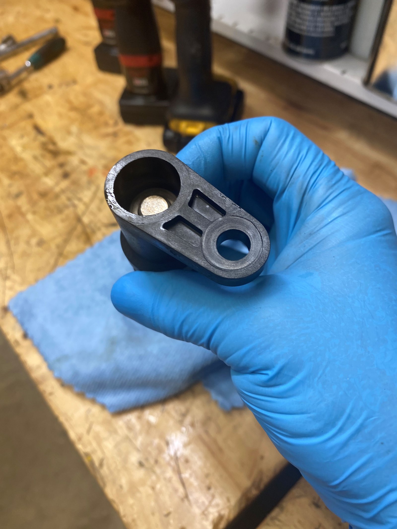
I plugged the water pump drive shaft hole. My TorqHead sensing unit is
installed temporarily until the owner's comes in from Canada. I want to
test oil pressure and all the holes need to be filled.
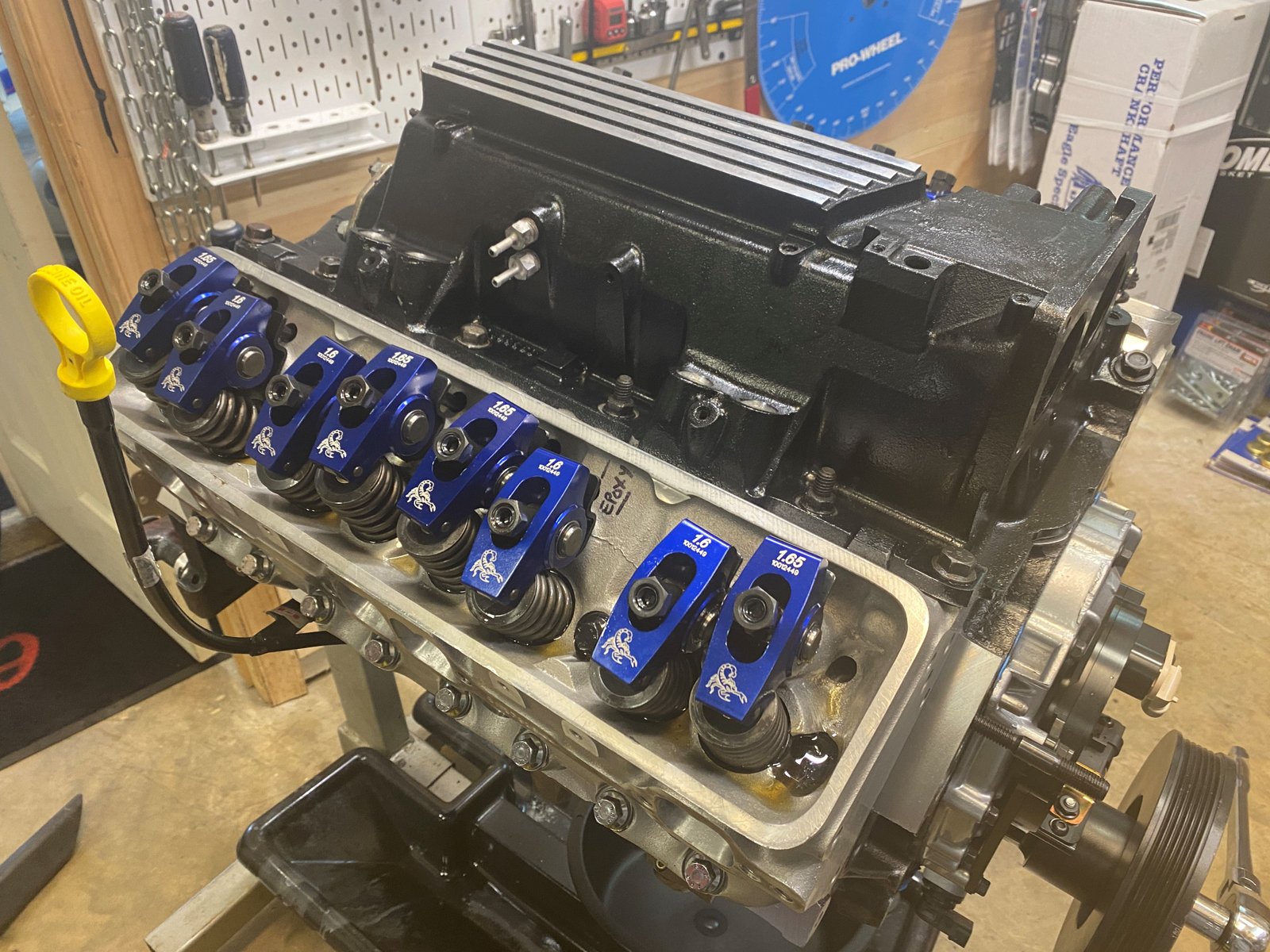
The heads after Dennis Staff finished working them over.
The valve springs checked out ok and will be good enough for the
camshaft. The heads received a clean-up decking and clean-up porting and a
valve job and set up of the valve springs.
One runner had a pin-hole leak into the water jacket upon initial vacuum
test. It was nicely epoxied.
MLS head gasket (.027" compressed thickness).
ARP head bolts
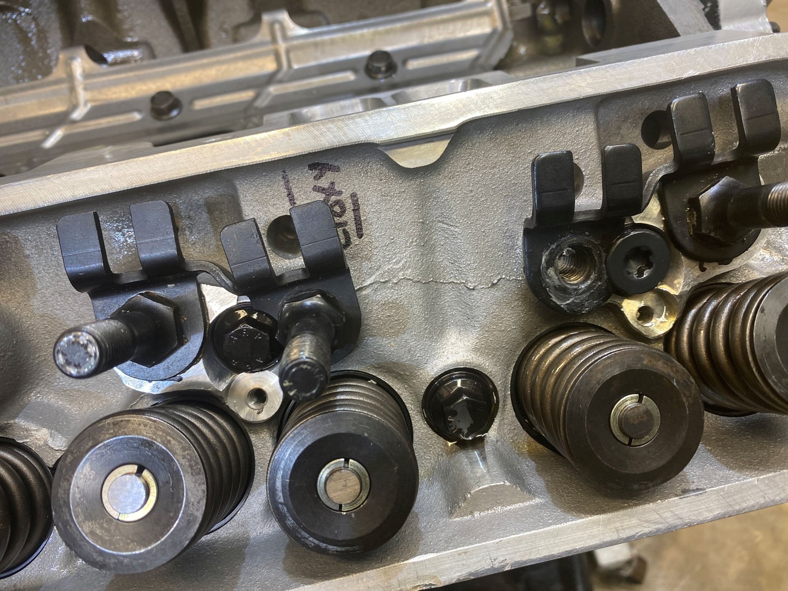
Installing pushrod guide plates. The rocker stud cannot be torqued
down fully because it is too close to the head bolt.
Luckily I have a flat headed head bolt that is supplied with Jesel shaft
rockers. I have a drawer full of these. Now the wrench socket can
engage the rocker stud for proper torque.
Now waiting on pushrods. The intake requires a shorter pushrod than
the exhaust.
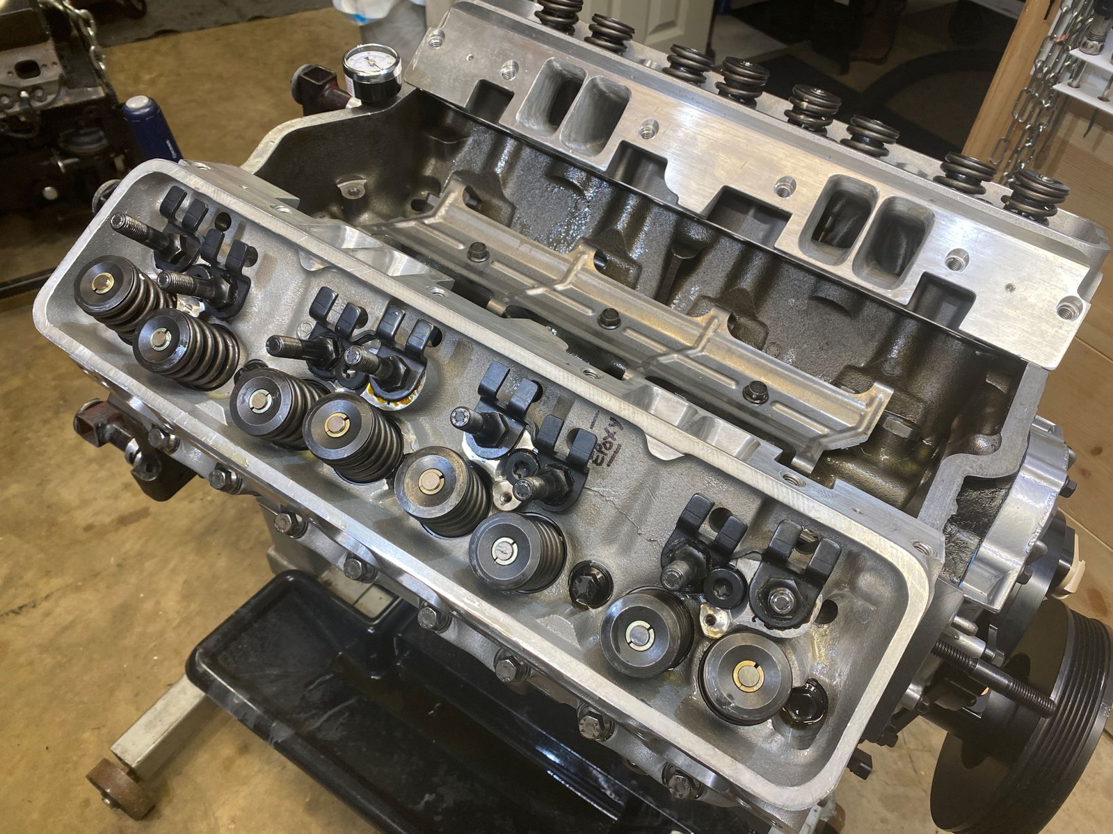
Here is another photo of the 4 head bolts that were swapped out to allow for
rocker stud clearance.
The exhaust valve pushrods ended up being 7.200" and the intake are
7.150"
Oil pressure test. New gauge. It's showing 50 psi and I usually
get 60 or more.
The old gauge = 60 psi.
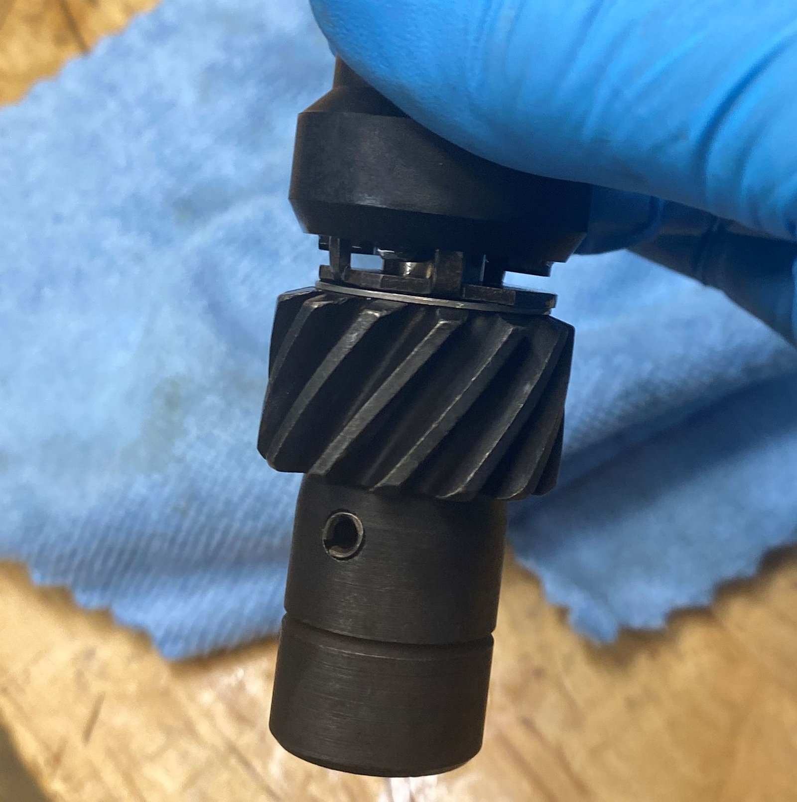
Used but good oil pump drive gear.
20 ft-lb torque and a washer to help spread the load.
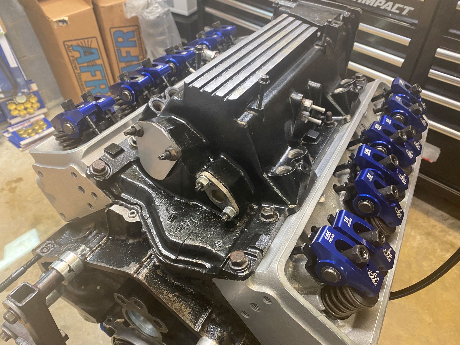
The intake manifold was clean but I wanted to verify under the EGR and PCV
cover. It has been cleaned up too. But I like to take out the core
plugs just in case it is all clogged up.
It was full of carbon under the plugs (from the EGR).
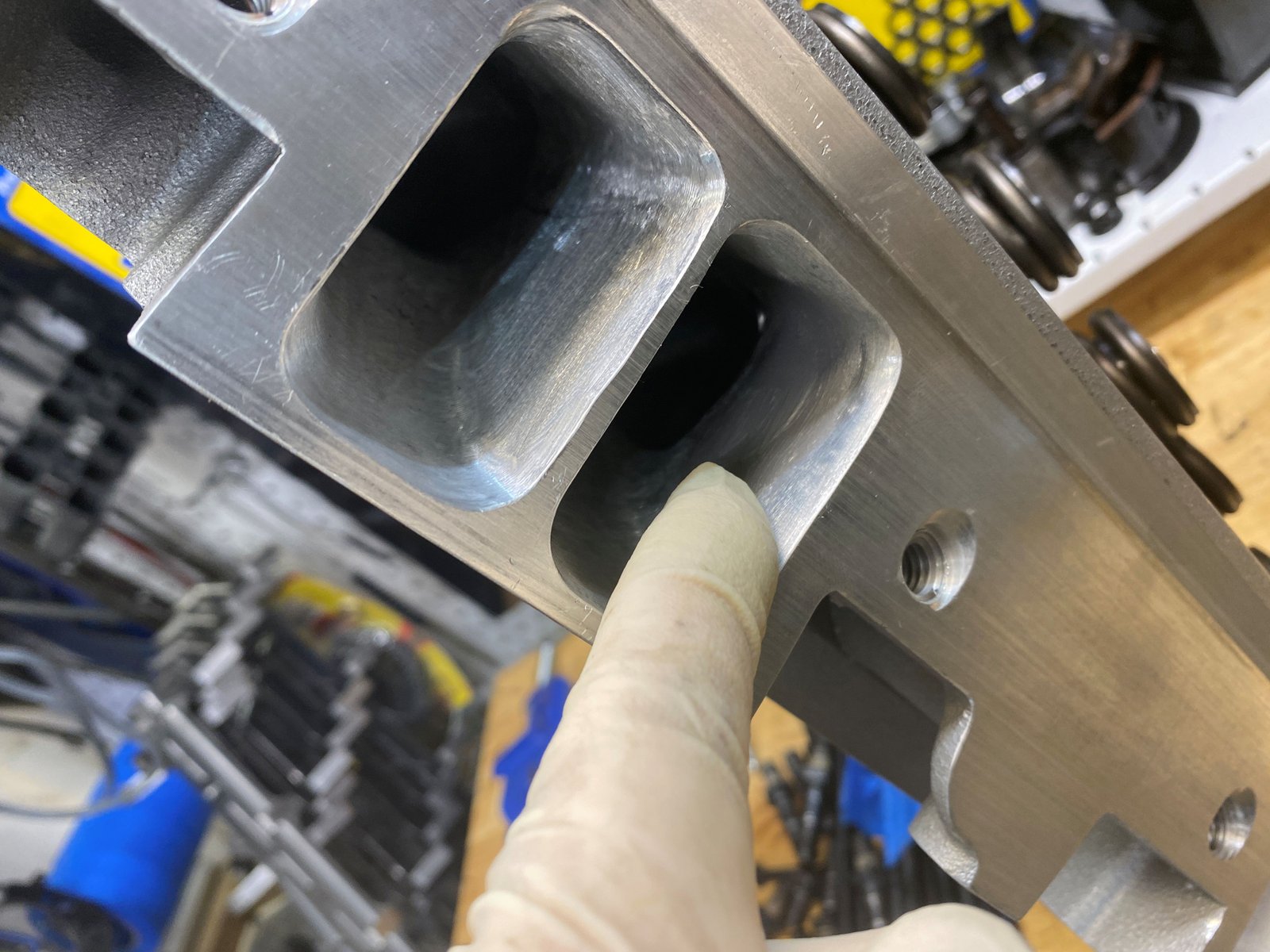
One last thing to do to this intake manifold: I test fit it to the
block and it was a very good fit to the china rail and the heads but the bolt
holes needed to be widened.
POR-15 ENGINE BLACK
TorqHead parts arrived. Install photos following....
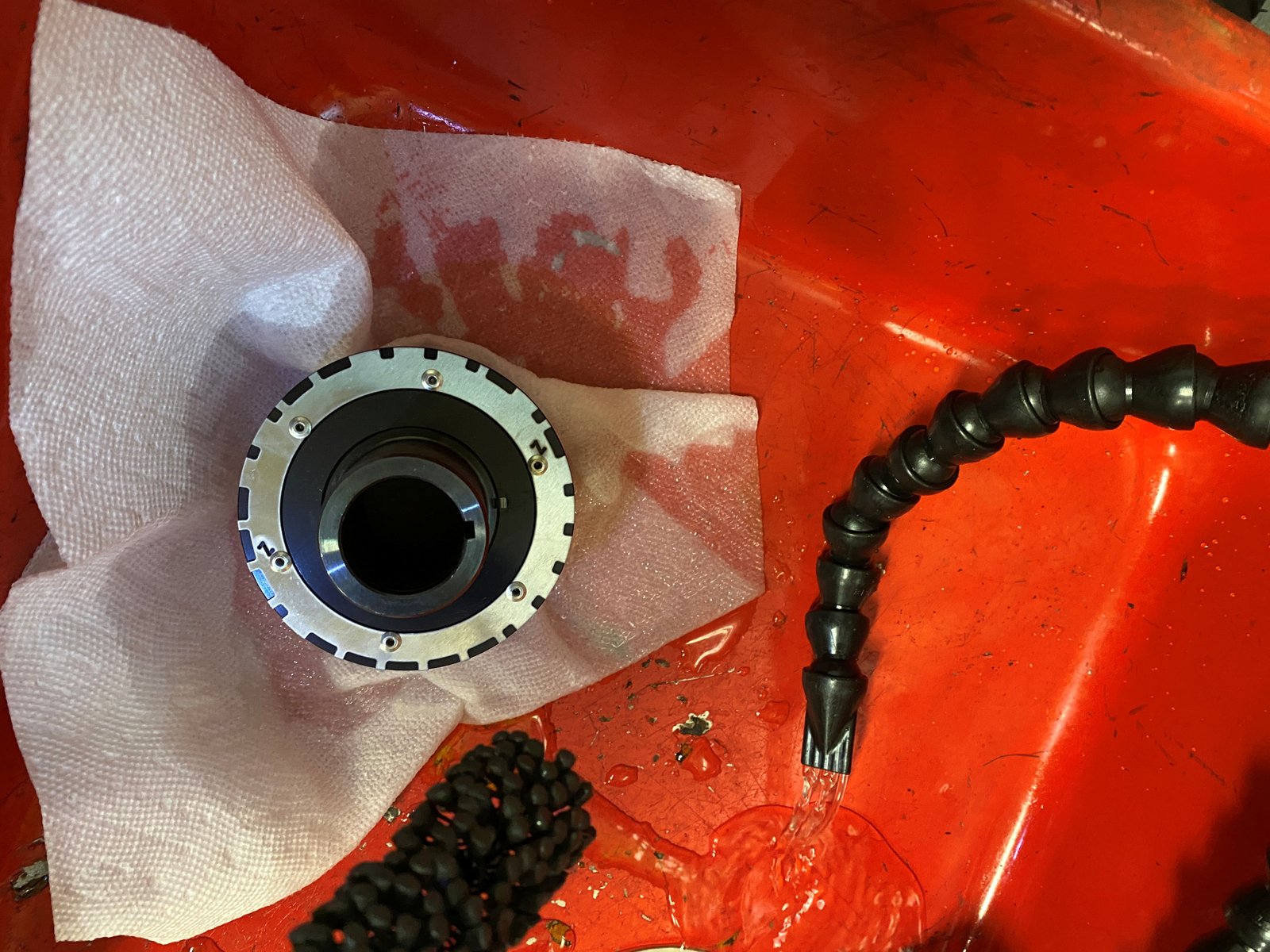
Here I make sure to put the spacer ring in and take a photo to serve as
memory/verification. On a 1996 LT1 (which came with a 4x reluctor) you
need to put the spacer in if you don't have the stock reluctor. This keeps
the hub at the proper distance for accessory belt alignment.
I honed the ATI hub just a bit to get it to .001" interference fit.
Normal small block Chevy damper install tool works here because the hub is
an ATI with a large inside opening to let the bulk of the tool fit. An LT1
hub only has a hole large enough for a 7/16" bolt.
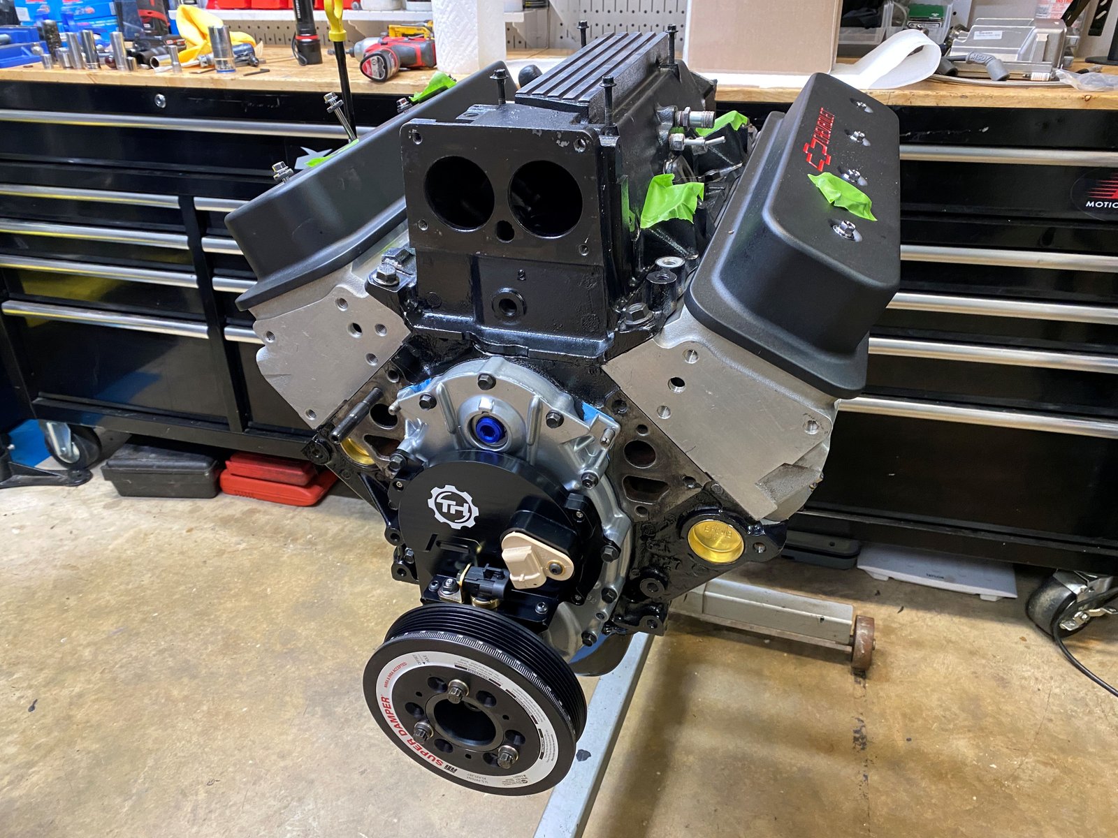
Pressed in all the way. Crank sensor still needs to be aligned and
centered and gapped with the tools provided by TorqHead.
Now see here how large the inside opening of the ATI hub is. I am very
happy when people use this type of hub.
Here I made sure the ARP crankshaft bolt would thread all the way in and not
bottom out.
ARP bolt goes in with confidence.
Tightened to 90 ft-lb
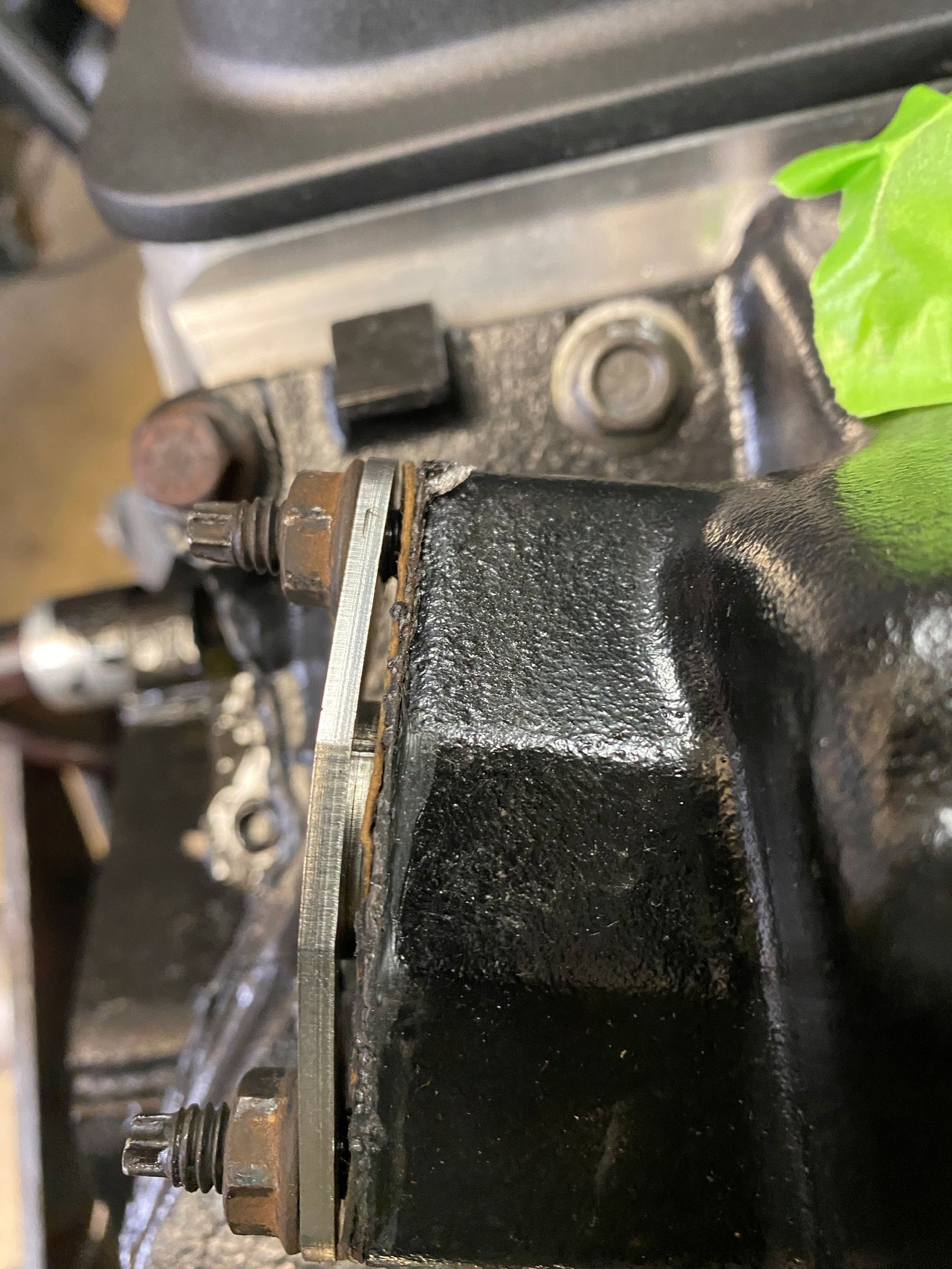
Making sure the valve cover bolts are trimmed (ground thinner) so that they don't
rub the rockers.
Also added this photo to show that I put a metal plate behind the EGR block
off plate to make sure it seals well.
Here is a suggested flexplate. This is a good quality but not all to
over priced neutral flexplate that is needed when having a neutral balance
rotating assembly.