|

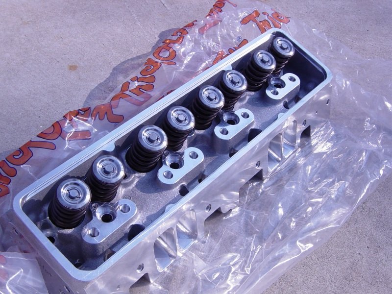
How about a nice cup of Ai. CNC machined and finished to
perfection Trick Flow LT1 heads.
|

Callies custom crankshaft. Notice the big block Chevy
nose. That idea may not be original but I got the idea from
Anders Envall's engine and his builder The Late Lennart
"Bagarn" Bergqvist of Autoshop Racing Engines.
|
|

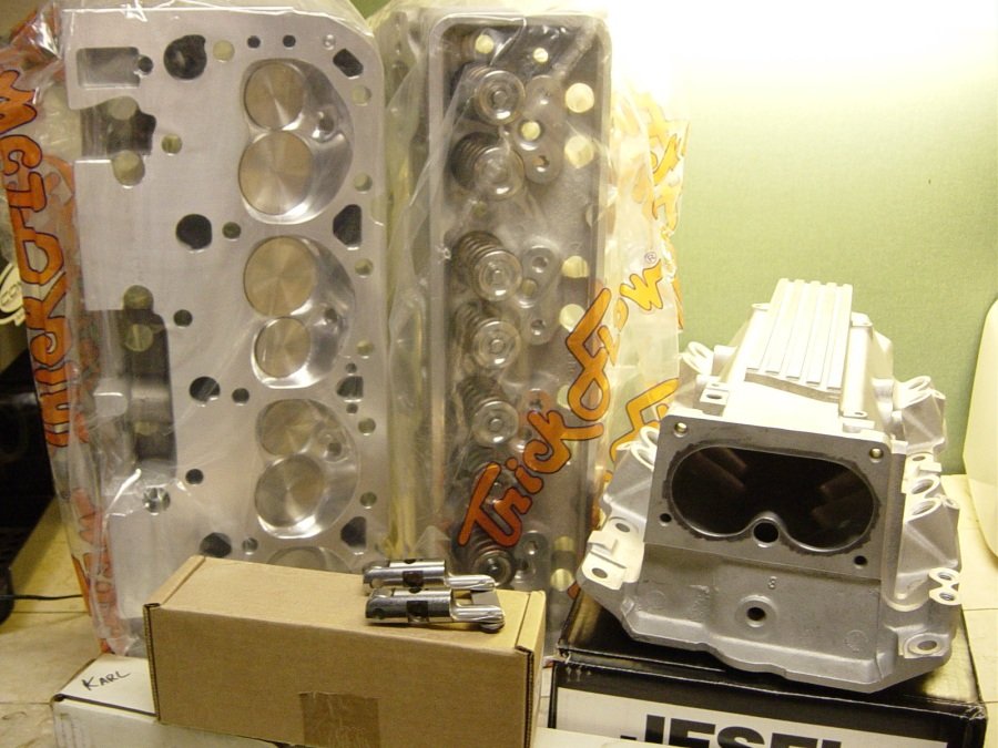
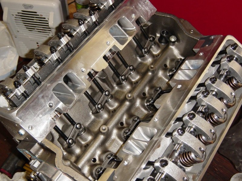
Ai was also relied upon to supply the valve train and ported LT1
intake manifold. The lifters are Morel UltraPro HIPPO
mechanical roller. The cam is custom and of a billet 8620
steel core. Of course you can see the Jesel shaft rocker
box. The heads have the CT1226 PSI brand valve springs with
Xceldyne Ti-17 retainers and machined locks and locators.
|

Oliver billet rods, (5.850"), Clevite H-series bearings, and
Callies Magnum crankshaft, (made to order).
|
|

Many aspects of this project are taken directly from knowledge
base of Anders Envall and the Blackout
SS project. ATI provides the machine work and
crank seal for a big block Chevy crank snout.
|

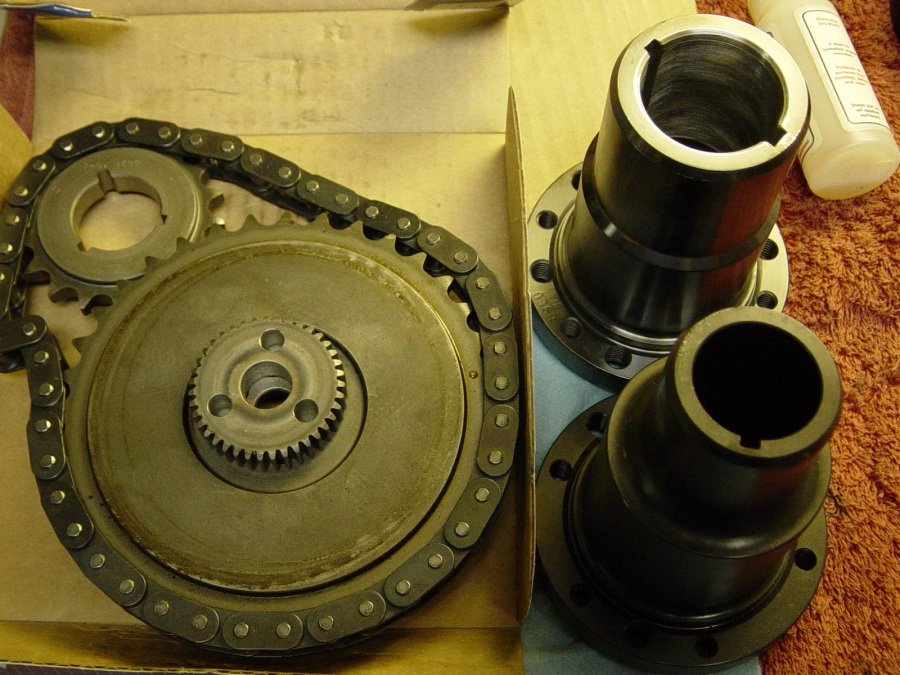
LT4 extreme timing set needs to have the crank sprocket machine
for the 1.6000" BBC snout. The ATI damper hub for LT4
BBC crank in rear and LT4 SBC in front.
|
|

Here is the foundation. It's an LT1 block machined by the
fine folks at Golen Engine Services, [LINK]
Chad Golen has been providing fully machined LT1 blocks to Ellwein
Engines and they have all been very well finished. This one
is align honed for Callies splayed main caps.
|

Another view of the Golen block. This is "as
delivered". It is probably very clean but I do another
scruby-dubby just to make sure.
|
|

After cleaning and oiling of the bock I do a test fit of one or
two piston/rod combos to see if more clearancing is needed.
Chad's blocks has all been spot on for "pre-clearance".
|

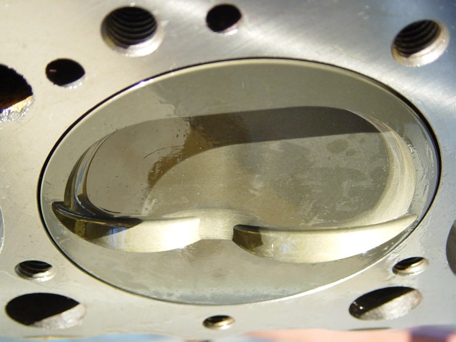
This is the custom blower piston that Mark McKeown of McKeown
Motorsports Engineering designed for this project. The plan
today is to mock up one rod/piston combo. This Oliver rod is oh-so-sweet.
|
|

2 spiro-lox per side. One shown here just for a pose.
While winding that thing in I immediately noticed that the piston
coating really is slippery. McKeown Motorsports Engineering
supplies all of my ROSS custom pistons.
|

OK, now the rod/piston is in #3 hole.
Next I will rotate the crank and check for clearance.
|
|

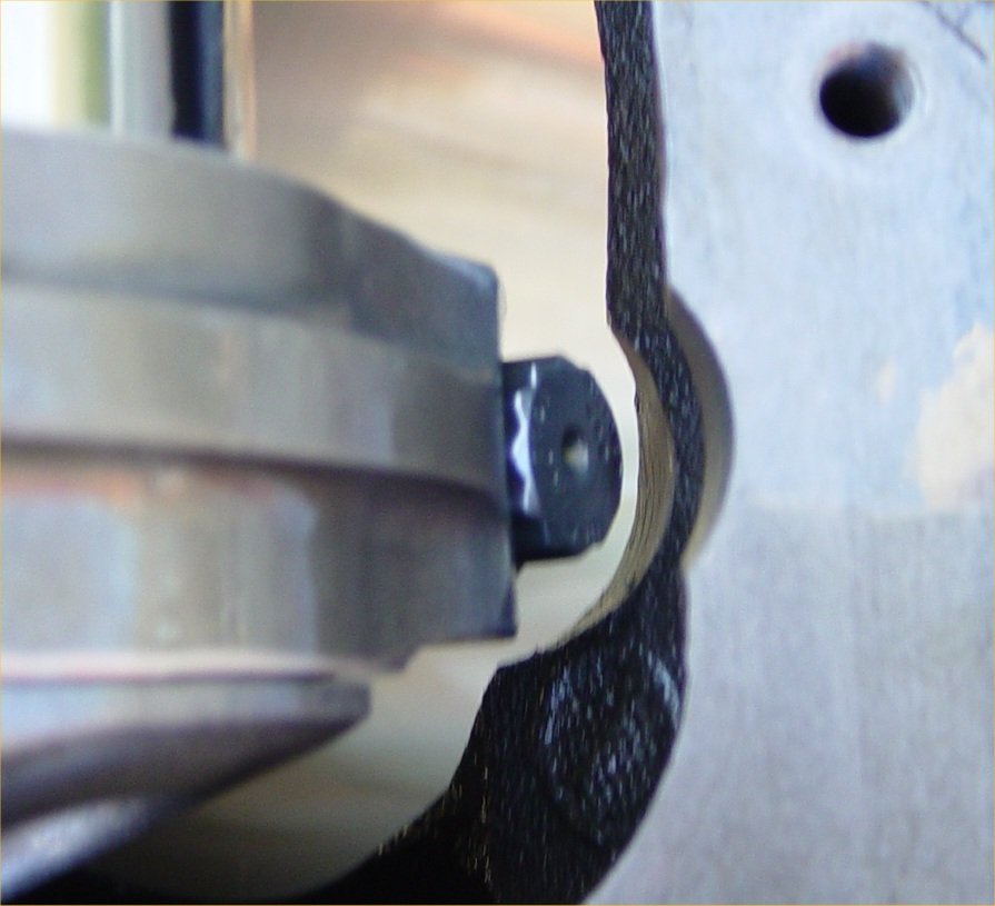
Piston comes out of the hole by about what feels like .010"
|

Very good here at the oil pan rail side
|
|

The other place is the cam side of the cylinder bottom, (the cam
interference will also be checked later). You cannot see it
but there is a mile of clearance.
|

And the other spot to check is the piston skirt and crank
counterweight at the bottom of the stroke. Looks good here.
|
|
The
next day
Cam bearing install and measuring main bearing clearance

Performance coated cam bearings being installed. For LT1
remember that the HELMS manual says the oil holes are installed as
follows: #1 at 1 and 5 o-clock, #2, #3, #4 at 5 o-clock, #5
at 12 o-clock |

Now preparing to measure for main bearing clearance.
The way I like to do it is to install the main bearings and torque
the main caps and measure the clearance of the main bearings and
subtract from the measurement of the crankshaft main
journals. I like .0020" to .0025" for 1,2,3,4
mains and .0025" to .0030" for #5.
The motor
is the "King 383" version and so is fitted with Callies
splayed main caps and ARP studs. |
|

Stick a dial bore gauge in and zero it out.
|

The micrometer is set at the crankshaft main journal reading of
(2.4480") which seems to be a .001" thinner than most
crankshafts. I am getting readings of .0030" to
.0040" of bearing clearance. Not good. I need to
order a set of .001" under bearings.
|
|

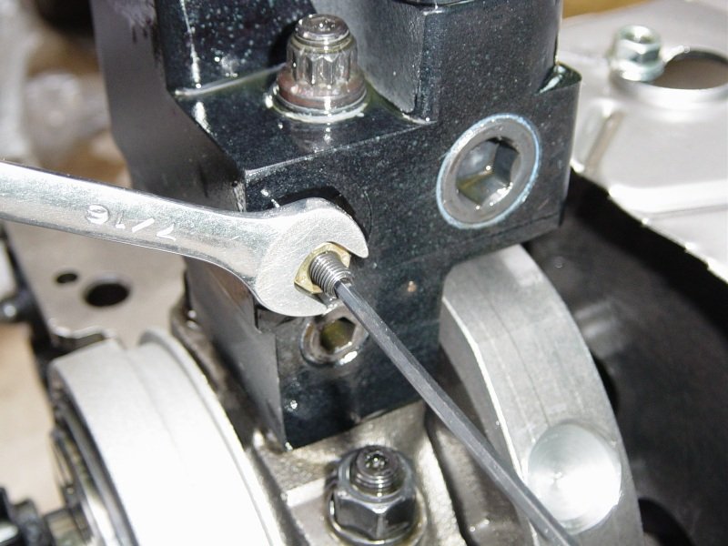
The flash is killing me. The best photo I can do showing my
stretch gauge and torquing the Oliver rod bolts, (7/16"
Oliver/ARP WSB). These need .0053 to .0058" stretch which
seems to be about 80ft-lb (or 30ft-lb and 40deg).
|

Again use the bore gauge and set to zero.
|
|

Tools of the trade. I
set the bore gauge in my digital caliper and the micrometer just
to make sure they match. The Oliver rods with Clevite
H-series bearings come in at .0025" clearance. That's
2.1015" rod minus 2.0990" main rod journal = .0025"
|
4-27-07
more assembly:
mixing
.001 and standard size main bearing for good clearance.
|

Since main bearing clearance was too big using standard size
Clevites I will mix these .001" under bearings with standard
size bearing halves. |

Some journals required .001" for both bearing shell
halves and some required the mix of .001 and standard. Main
clearance is now .0015, .0020, .0020, .0020, .0025" from #1
to #5-thrust. |

Then I installed the Callies Magnum crankshaft and set the thrust
bearing shells and crankshaft endplay is .005" |

I want to file the piston rings but I'm going to ask around to all
the engine builders I know for advise on ring gap. So while
waiting to make my decision on gap I can put the cam in and the
timing gear and degree the cam. |

Cam handle tool helped slide it in |

This is a Cloyes crank sprocket that has been machined to fit on
the BBC snout. Also the keyway needed to be broached.
Jimmy Reichard at Reichard Racing did this work. I failed to
communicate that I also needed the 1/4" key-way 180°
opposite of the stock key-way. |

The sprocket on the left is from the Cloyes 9-3151 timing set and
the sprocket to the right is the GMPP version. I have them
shown side by side to show the difference in BBC crank snout size
to SBC snout size. |

I took the sprocket back to Reichard Racing and now it has the
1/4" keyway. |

Rats. My install bushings are not wide enough for the BBC
snout so this is as far as I can get the sprocket to go. I
need a wider bushing. Will shop around Saturday 4-28-07. |

Now to the cleaning of the Oliver rods. The protective
shipping oil needs to be removed. I re-oil them with WD-40. |

Assembling piston to rod. |

This took about 1 hour. |
|
4-28-07
degree cam, file fit rings, install piston/rods onto crank: |

Time to put on the timing gear and degree the cam. This is a
very much needed check because the crankshaft has custom keyways
and the crank sprocket also. This photo is of the cam
sprocket and chain and water pump gear for the Cloyes 9-3151
(extreme duty LT4). |

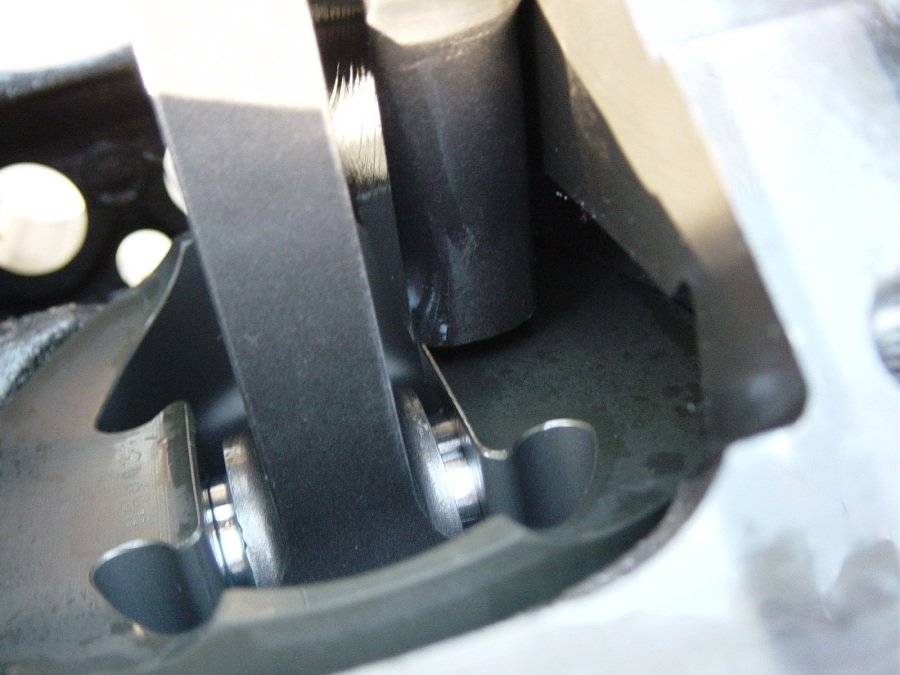
Went to the hardware store this morning and bought a 2" I.D.
pipe to help me press on the custom machined sprocket. But it
won't go as far as needed. It's about .020" away from
fully flush with the crank shoulder. The sprocket needs to
be honed out to a larger inside diameter. I can still degree
the cam though. |

Close up of the timing set installed, (but the crank sprocket is
not fully seated). |

I degreed the cam with the single roller extreme timing set and it
was 2 deg retarded. I replaced that timing set with a
SBC/BBC double roller from Cloyes, (a mix of timing set 9-3145
with crank gear S-101BB). The double roller set up was 1 deg
advanced. For now I'm going to stick with the double roller
set up. That means Kent will need to use an electric water
pump. |

Now I begin the file fitting. This top ring is of chrome
steel and 1.2mm. The rings are a custom set from Total
Seal. 1.2/1.2/3.0mm. It came with low tension
oil rings but I swapped those out for standard tension. I'm
gapping at .024" top and .026" 2nd. |

It's a funny looking top ring. I do the top ring and then
the 2nd ring and leave them in the cylinder bores. |

Then when it's time to put the rings on the pistons I do the oil
rings, then pull the 2nd ring from the bore, then pull the top
ring from the bore. All in a nice sequence. |

Piston ready to go. |
Filed #1
cylinder top piston ring too wide. Have new set of rings on
rush order from Total Seal. Will continue with engine
assembly and get the heads on and measure for pushrod
length. When the new ring set arrives I'll take the left
side head off and pull #1 piston and re-ring it. Also had #3
and #7 rods bump the bottom of the block and need to take the
pistons/rods/crank out and grind and clean the block in that area.
Check back Sunday 4-29-07 for update. |

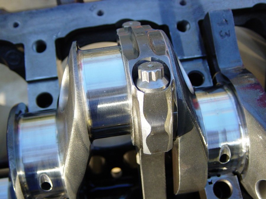
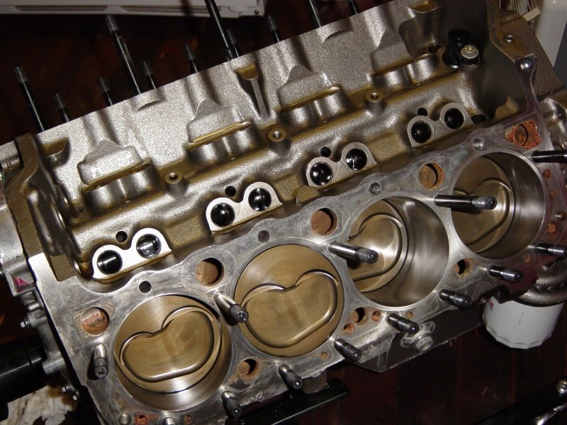
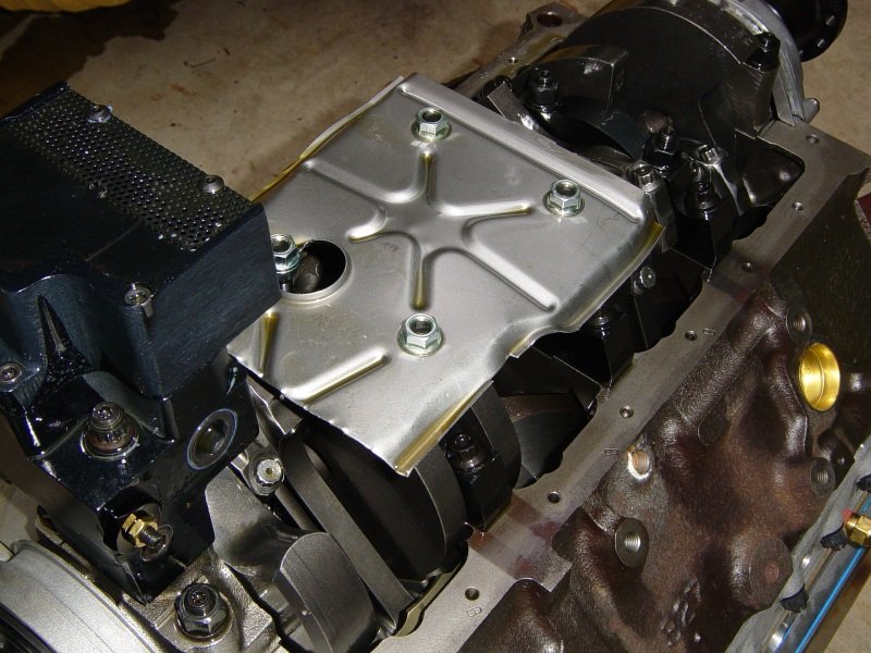
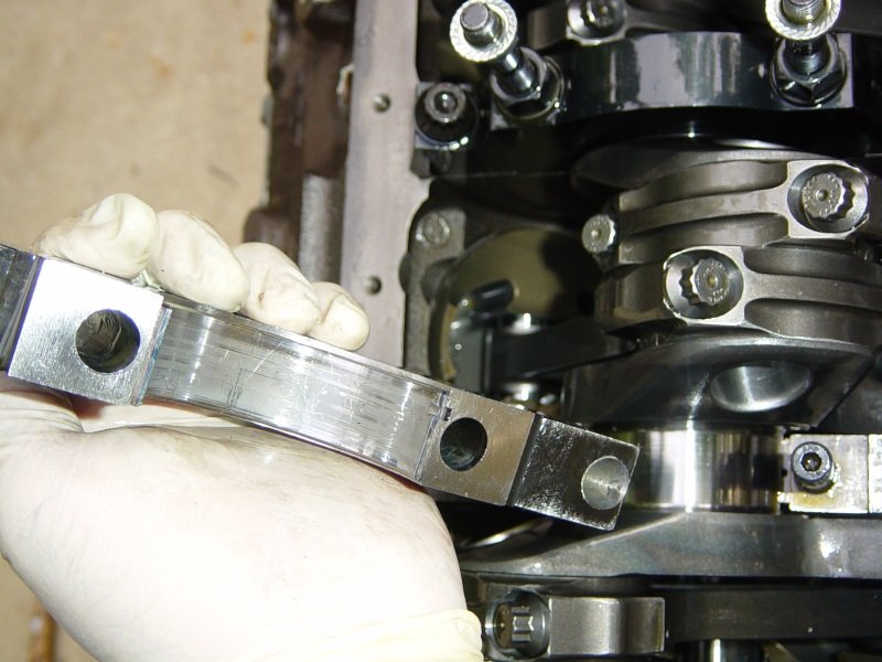
In the mean-time, here are photos of the fully assembled bottom
end. Oliver billet I-beam rods and Oliver/Callies splayed
main caps with ARP main studs/bolts. |

Pistons 2,4,6,8. I took the time to check where the pistons
were with relation to the block deck and they are at.
Tah-Dah! 0.000" (Zero). Now I plan to use an
"off-the-shelf" Cometic MLS head gasket (.040") |

I took the whole motor apart and clearanced the block in the areas
where the conn-rods hit. After a thorough cleaning and
reassembly I think it's time to torque the rod bolts. The
Oliver rods use 7/16" ARP WSB bolts which require .0053 to
.0058" stretch. It takes 90ft-lb for that with ARP bolt
lube. |

I don't think I've shown the double roller timing set. Here
it is. |

In preparation for Sunday final assembly I decided to clean these
mechanical roller lifters and then soak in oil overnight. |

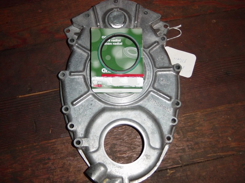
The next day: This is Kent's custom machined timing
cover. It has the crankshaft hole machined wider by ATI,
(the transmission company). ATI also provided the seal. |

Here is a close up of the reverse face of a J. F. Kennedy
U.S.A. Half Dollar. |

Head studs cleaned from packaging oil and threads sealed with
"Right Stuff" RTV. |

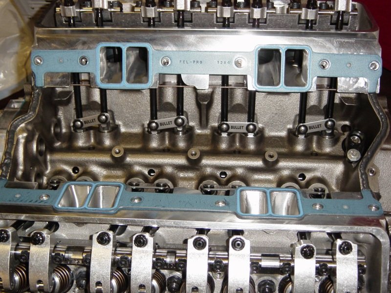
Advanced Induction CNC ported Trick Flow cylinder heads. I'm
using a FelPro head gasket right now for the dyno testing and will
install multi-layer-steel (Cometic or Flatout) brand prior to
shipping to Sweden. |

Oops. Cannot use the top 4 ARP head studs with a JESEL shaft
rocker system. JESEL supplies very compact headed bolts to
use instead. I torqued the bolts and studs to 75ft-lb with
ARP moly lube. |

Now is a good time to check for pushrod length and also rocker tip
to valve tip geometry. Intake rocker needs a 7.700"
pushrod and the exhaust needs 7.750". |

First check with .100" shims under shaft rocker stand.
This has the rocker tip riding too far "outboard" of the
valve tip. |

2nd check without the shims. Perfectly centered rocker tip
to valve tip. |
Now I wait
for my Total Seal ring set so that I can re-do the ring gap for #1
cylinder. I know the pushrod length needed and can have Ai.
send their house brand of .375" OD chromemoly pushrods.
Until then I can go over the small details of the engine such as
rear main seal housing and proper gerotor oil pump drive shaft
length. I can also paint the block. The motor will be
tested using the GMPP LT4 carburetor intake manifold and rear
mounted distributor. The dyno testing is to make sure all is
well with the engine prior to shipping. |

My favorite oil pump. This is an high
tech gerotor oil pump by Titan. The gerotor design is less
prone to cavitation, (the biggest problem for spur gear oil
pumps). Hopefully the pump will provide a solid 65psig at
WOT. |

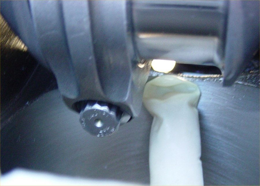
The pump comes with a tool steel quality drive shaft and it must
be trimmed to fit. I whittle it down to fit into the LT1 oil
pump drive gear and also shorten it just a hair. |

The drive shaft is shown here. It cannot be too tight.
When the motor heats up and things get all crazy with 25psig of F2
blower boost then the shaft won't bind. |

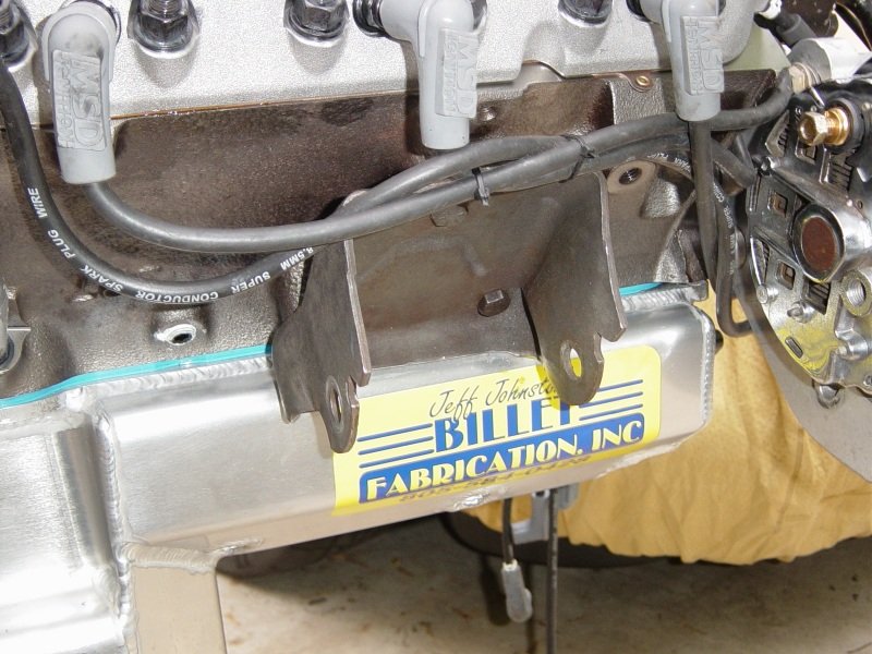
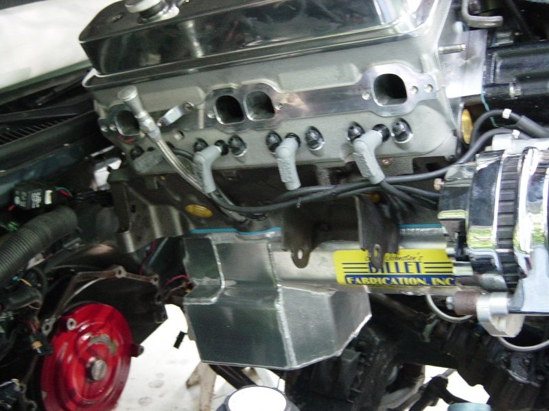
The OIL pan of OIL pans. |

This is a Billet Fabrication SBC pan built especially for Ellwein
Engines. It was test fit already on a customers Impala SS
and only a few modifications are needed to the chassis....that is
mostly just a motor mount trim. There is a very big
"power" kickout on the right side which is for crank
windage control. The sump is 8.5" deep and very wide. |

The power kickout. |

Test fit onto Kent's King of Spades 383LT1 |

It fits very well. There are very few hold down bolts
because of the stroker notches and the windage kickout. The
super thick flange helps to press down on the oil pan
gasket. I'm going to try this pan on the dyno without
RTV. I think it will not leak. |

Received more top rings from Total Seal UPS overnight.
Replaced #1 piston top ring which was filed too wide by
accident. Pushrods Ai arrive soon. |

Time to button up as much as possible. I'll put the oil pan
on and pre-lube the engine and also check oil pressure. The
Titan pump is adjustable. |

Oil pan bolts on and squishes the FelPro gasket very well. I
am not using RTV. |

Here is the pressing on of the ATI big block Chevy crank damper
hub onto the Callies big block Chevy crank snout. |

The hub is on. Oil pan is on. All oil plugs are installed.
OOPS. Forgot the
windage tray. Will take pan off and install tray as well as
up the oil pressure. |

Flipped the engine upright and filled with 6 quarts of Shell
Rotella non-detergent 30 weight oil. No leaks that I can
see. The drill pre-lube spin of the oil pump only gives me
57psig. I will adjust the pump to push up the relief set
point. |

Advanced Induction sent CV
products 7.750" and 7.700" 3/8" diameter
pushrods. These are thick and stiff. |

Ai widened the pushrod
holes just for these 3/8" O.D. pushrods. |

All the Jesel rockers are installed and lash is set to .015"
cold. That should widen to .02x" hot. |

I took the oil pan off in order to turn up the relief spring set
point. I turned that adjusting allen 2 full turns
clockwise. Now I have 63psig oil pressure. |

Then I cannot forget the windage tray. |

Always have to trim these for either the oil pump or for the oil
pan. I added a 4th Milodon taller main stud to help keep
this tray steady. |

Before installing the oil pan I widened the dip-stick hole. |

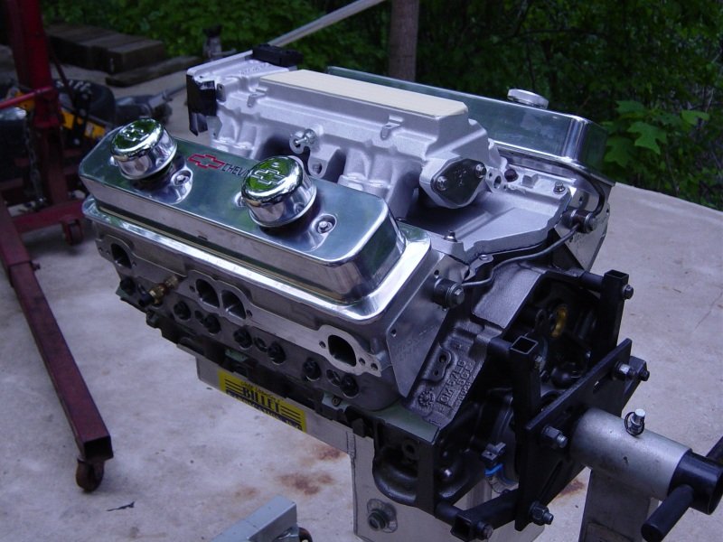
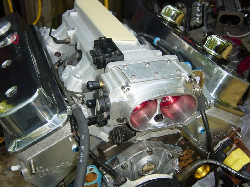
Then I installed the dyno intake manifold, the GMPP LT4 carburetor
manifold. |

Almost finished and ready for a trip to McKeown Motorsports engine
dyno. |

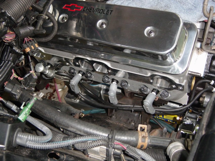
Those a brand new ProForm valve covers. I don't think I'll
send those to the dyno to keep them from getting scratch.
I'll find a set of valve covers from one of my cars to use
instead. |

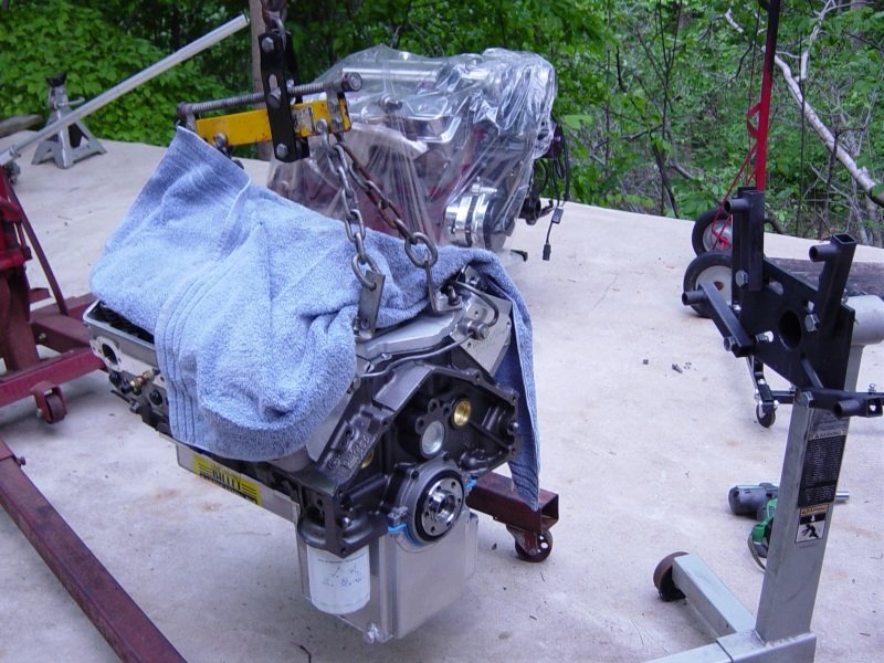
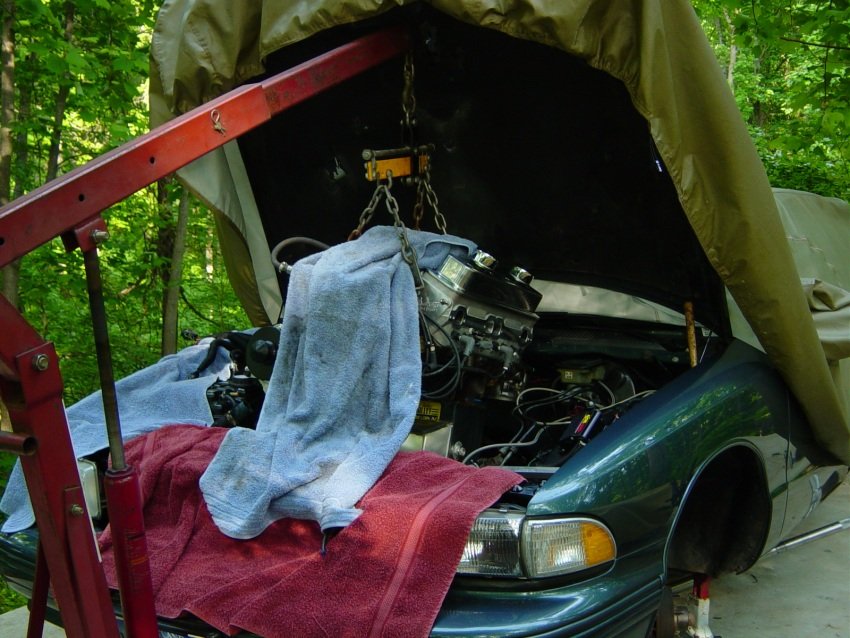
5-3-07: Trucking motor to the engine dynamometer. I borrowed
valve covers from my Impala SS and a steam pipe for the heads. |

If you click on the photo to see the larger photo you should be
able to see the timing pointer. I checked the pointer position
and it's dead-nuts-on top dead center. |

I wrapped her up some more and set it in the bed of my Chevy
Silverado. |

Ready to go. |
|
Now that
dyno testing is satisfactory, MME will begin work on the
crankshaft girdle. A new web page has been made to show the
progress of that. [LINK] |
Before the
motor ships to Sweden it should have an inspection and certainly
the Cometic head gaskets should be installed. See below. |
|

1st job for the inspection is to take the heads off. This
photo is taken just prior to taking off the Jesel rockers.
|

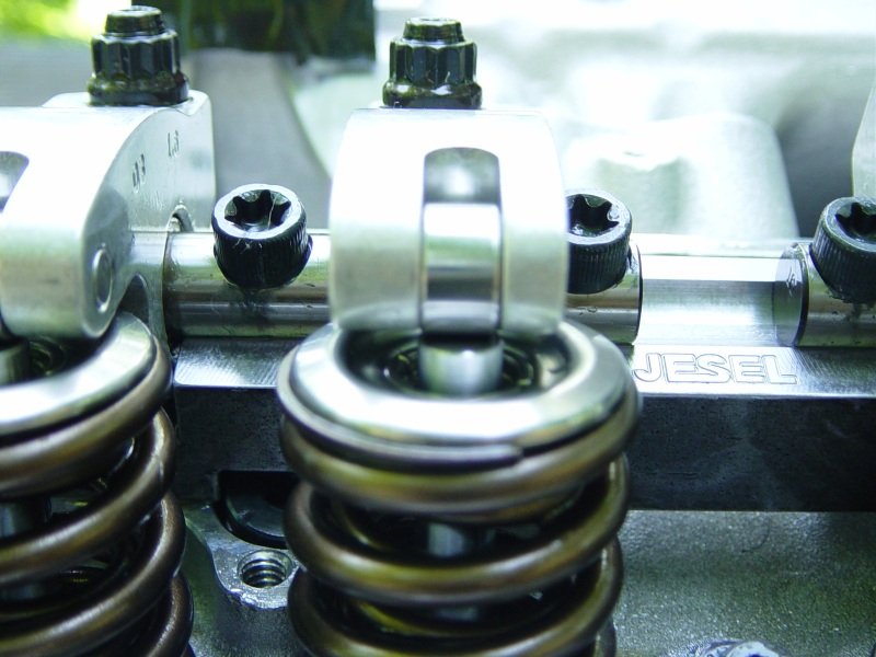
The valve tips have a good indication of proper geometry from the
Jesel rocker tips. The witness mark looks to be right in the
center.
|

Heads off. Cylinder walls and pistons look super!! The
spark plugs looked very good also. |

The gasoline gunk came off pretty easy due to the hard anodized
piston coating. Taking a break tonight but later I'll have
to take out the head studs and clean the block head deck and
install the Cometic gaskets. After that I'll check the
bottom end and finally install the motor into my 95 Impala SS for
one final operation check. |
|

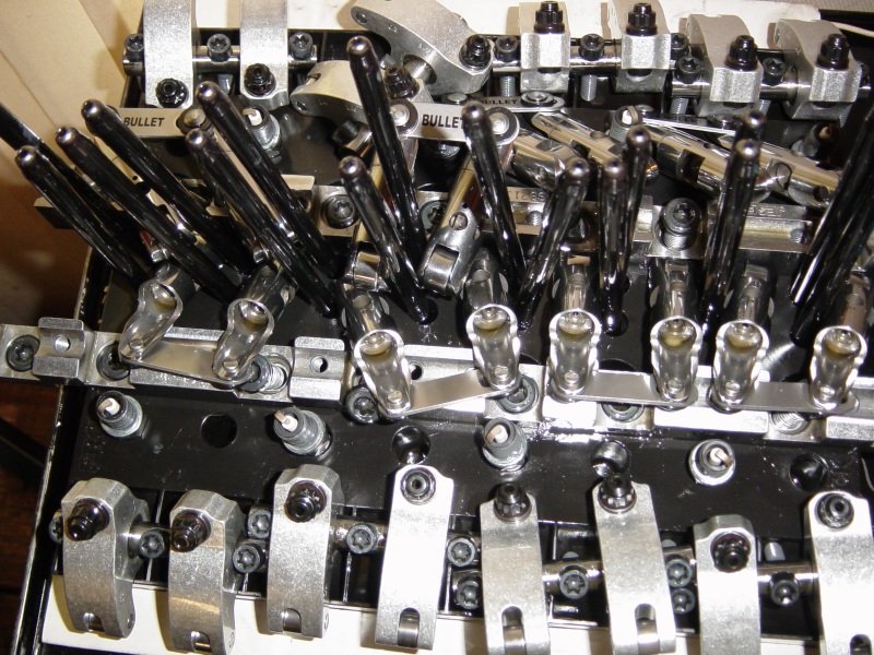
This is my valve train organizer.
|

I installed the Cometic gasket and now I'll install the shaft
rockers. |

Turn the crank to where the intake and exhaust of a cylinder are
on the cam base circle and just bolt on the rocker pair. No
adjusting needed if you already had the lash set. Shaft
rockers make pit maintenance much easier. |

A photo of the very pleasing to the eye valve train components. |

Getting ready to install the intake manifold. All surfaces
clean with "brake-clean" and "The Right Stuff"
Permatex RTV at the ends. |

Intake manifold bolted on. How do you like the Edelbrock
AirGap? |

Kent's engine needs to be flipped upside down for the oil pan
removal and bottom end inspection. That 350LT1 in the
background was in my Impala SS and some of the parts from that
motor will go on Kent's motor during testing. |

Do you like the valve covers? I do. |

Oil pan off. Here is the bottom end. It looks
good. But there was a little bit of metal in the oil pan
that looked like small pieces from the windage tray. The
piston and cylinder walls look super! |

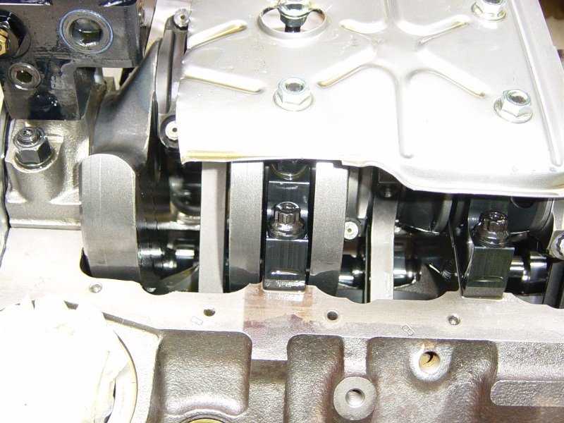
Some close-ups of the bottom end. It looks super clean. |

More bottom end photos |

Windage tray off for a better view. |

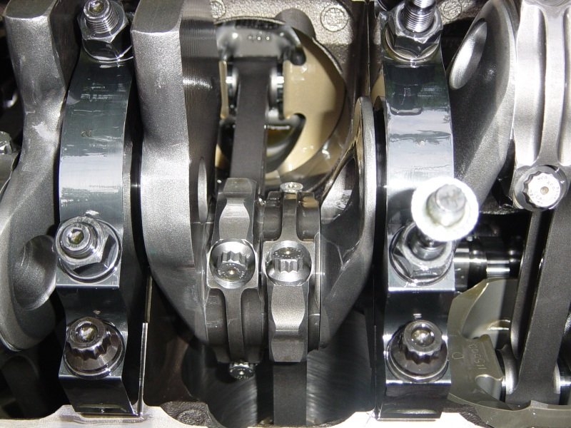
Here is rod bearing #8. It looks very good. I can
still see my bore gauge marks. |

Here is main cap #2. It looks pretty good. |

Now here is proof I did not forget to turn back the oil
pressure. I had turned up the oil pressure during the
initial build. Well, on the engine dyno the oil pressure was
110psig at 6500rpm. That pump was pumping too much.
Now I am taking the oil pressure adjuster back 2 turns to where it
started at. Titan sets them prior to shipping and I ask for
65psig. |
So now the
oil pump is set back to original relief set point. The
bottom end is buttoned up. The oil pan is on with RTV.
In a few days I will install the motor into my 95 DGGM Impala SS
for final testing. |
|

I'm transferring parts from my 350LT1 onto
JeZus2 (The King of Spades). Opti, water pump, throttle
body, hoses, etc
|

A fuzzy photo but you can still see something I just
noticed. The rockers on the left head are just a tad
"off" They ride the valve tip a little bit
off to the left (in this photo).
|

I can take off all the rockers, (a quick and easy process).
I loosened and pushed the shaft stand a little bit in the
direction that would make the rockers more center. |

Now the rockers are close to being aligned (fore and aft). |

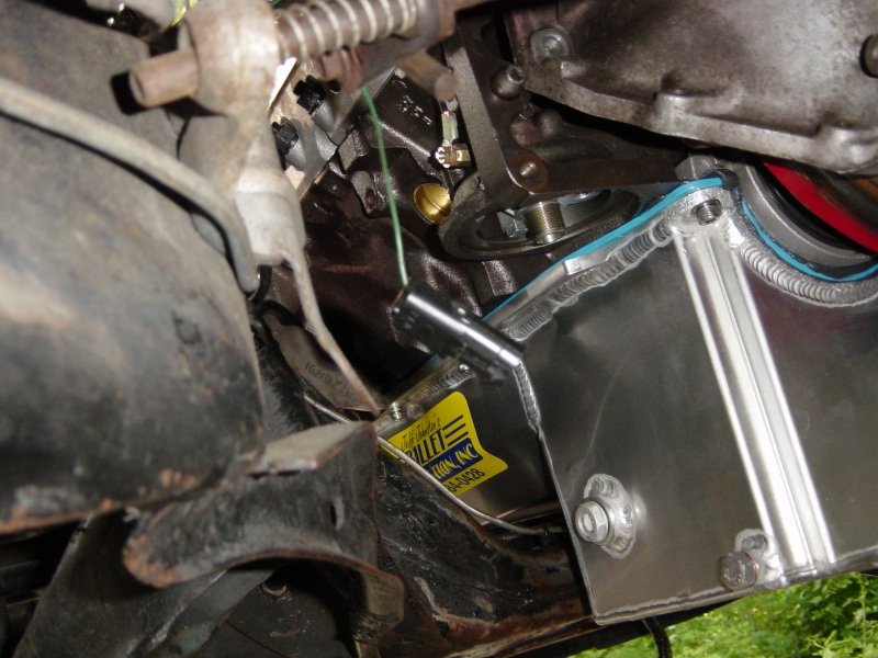
Now to address the oil pan to motor mount bracket
interference. Only on the right side. The bracket
touches the windage kickout of the Billet Fabrication oil
pan. Just a little. |

So I just took a grinder to the bracket and cleared away just
enough metal and now in bolts to the block without touching the
oil pan. |

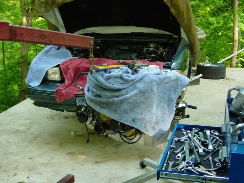
Tuesday 5-22-2007. I really want to see if the motor will
fit in an Impala SS engine bay with the big oil pan. If it
doesn't fit then all is not lost. . .I can use the Ellwein/Stef's
oil pan. But I really like the Billet Fabrication pan.
So do you notice anything missing on the motor right now that is
essential to have prior to installing the motor? (very embarrassing). |

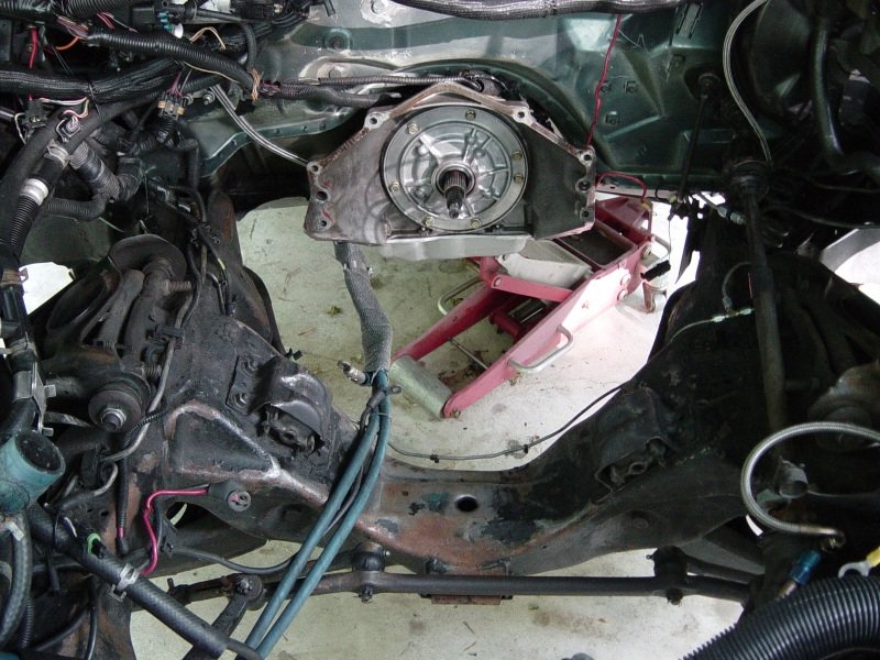
Engine bay with lots of room for an engine. I did not forget
to install the Yank torque converter. I just don't have a
photo of it. |

At this point I'm wondering if the big sump in the oil pan is
going to allow me to shoe-horn this motor onto the motor mounts. |

You might notice that very important component (missing) in this
photo. |

Oh YEA! She went onto the mounts without any trouble. |

A little close up of the oil pan and it's fit into the Impala SS
chassis. The motor is tilted rear down in this photo. |

I'll stop at this
point. Today's goal was to get the motor on the mounts and
bolted to the tranny. That did happen and it was easier than
I had hoped. There was one oversight though and I'll address
that tomorrow. |

The next day. Ha! the flexplate slips up and in
without having to pull the engine back out. The tranny is
not bolted to the engine yet so there was ample room to reach the
flexplate bolts.
|

The trans and the torque converter are all bolted to the
engine. This is how far down the oil pan sticks out under
the crossmemeber. |

Side view. |

Front view. |

Hoping that the starter will fit. I test-fit the starter a
few months ago on a block in the shop and I had to remove some
metal on the big mounting flange. The starter body is
clocked to where I think it will fit the best. Passenger side long
tube headers, (G-hann). |

The oil pan fits nicely. |

One day I would like to have my 8 year old G-hann headers
re-coated. |

I could not get the MSD
starter to work. It was just too big and too close to having
terminals touching the engine block and dipstick. I called Billet
Fabrication's Jeff Johnston and he said to get a Tilton mini
starter. |

Even though this Tilton starter is small, I still need to take it
apart and insert the two pieces past my headers and the big oil
pan |

Stick the motor up in there first. |

Then install the mounting flange to the starter motor. |

The motor just needs a few
odds and ends prior to start up. |
I loaded in
an old PCM tune from Ed Wright for a solid roller 383 with 4L60E
from back in Y-2003 and the Tulsa ISSCA Nats. That tune
should be close to what is needed for this motor. I started
up the motor and it runs well and lopes quite nicely. This
weekend will be used to street test the motor.
May
26th: This motor is a monster even without the blower.
Ai provided a very good heads/cam package. The street
testing was fun. Oil pressure is good. No water
leaks. No oil leaks. Here is a start-up and idle video
for you.
[Right
click save as]
|
|
Aug 10th.
Getting ready to ship motor.
Have been waiting for some custom work such as a crank
girdle. I performed a 2nd bearing inspection for
peace-of-mind. The motor was run a few days on the street
and at the track. It ran very well. But my 4L60E broke
while at the track and made squeaking noises. To make sure
that was not from the motor, (cam or bearings), I ran the motor
without the tranny attached and it sounded fine. But here is
a visual inspection also.
|

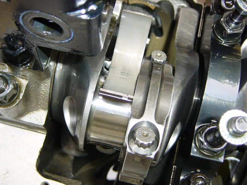
#1 main cap removed and at first I was worried. The bearing
looked burned at the edges. The crank looks fine. But
the dark spots at the edge of the bearings look burned.
Well, I forgot that that is what the bearing looks like brand
new. See the brand new bearing on top and the used bearing
below it.
|

The other main bearings looked fine and this thrust bearing has no
marking on it what-so-ever, (except the marks from the dial bore
gauge). |

The rod bearings all look pretty much like this.
|

Motor is packed and ready
for export to Sweden. The crate meets E.U. specifications. |

Ready for delivery to
Lufthansa
|

Motor now in Umea Sweden and installed in Kent's Impala SS.
Test fitting of a custom made crankshaft support. Lots of
things in the way. I hope to do what he is doing to one of
my cars here in the U. S. A. |

Will if fit under the hood?
|